


67
TWO STAGE NON--COMMUNICATING
127A/226A
These units are a low cost 2--stage option that is
non--communicating utilizing 2 stage scroll technology. These
units require Performance Boost furnace (313AAV, 353AAV),
variable speed furnace (355AAV, 315AAV) or new model variable
speed fan coil (FV4C). Variable speed fan coils prior to the FV4C
will NOT be rated with the new Legacy Line two stage units as
they are not capable of meeting the air flow requirements necessary
for rating. These are designed to operate with basic 24 volt
thermostat inputs.
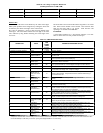
Operating Ambient
The minimum outdoor operating ambient in cooling mode is 55_F
(12.78_C), and the maximum outdoor operating ambient in
cooling mode is 125_F (51.67_C) when operating voltage is 230v.
For 208v applications, the maximum outdoor ambient is 120_F.
NOTE: Units operating at high stage operation, 208v (or below)
line voltage and at an outdoor ambient of 120_F (or greater), may
experience compressor trip.
NOTE: This product is not approved for low ambient cooling at
this time, and no low ambient kit is available.
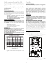
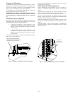
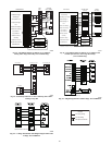
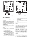
Airflow Selections (ECM Furnaces)
The ECM Furnaces provide blower operation to match the
capacities of the compressor during high and low stage cooling
operation. Tap selections on the furnace control board enable the
installing technician to select the proper airflows for each stage of
cooling. Below is a brief summary of the furnace airflow
configurations
1. The Y2 call for high stage cooling energizes the “Cool” tap
on the control board. The grey wire from cool tap is connec-
ted to tap 5 on the motor. Refer to the furnace Product Data
to find the corresponding airflow. If the airflow setting for
high cooling needs to be switched from tap 5 to a different
tap, jumper aconnection from the cool tap to the desired tap
so that the Y2 signal is communicated via the cool tap to the
desired speed tap.
2. The Y1 call for low stage cooling energizes the “Fan” tap
on the control board. The red wire from the fan tap is con-
nected to tap 1 on the motor. Refer to the furnace Product
Data to find the corresponding airflow. If the airflow setting
for low cooling needs to be switched from tap 1 to a differ-
ent tap, jumper a connection from the Fan tap to the desired
tap so that the Y1 signal is communicated via the Fan tap to
the desired speed tap. The Y1 setting will also govern the
continuous fan airflow for the furnace.
Refer to the literature for the furnace for further details.
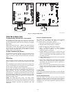
Airflow Selection for Variable Speed Furnaces
(non--communicating)
The variable speed furnaces provide blower operation to match the
capacities of the compressor during high and low stage cooling
operation. The furnace control board allows the installing
technician to select the proper airflows for each stage of cooling.
Below is a summary of required adjustments. See furnace
installation instructions for more details:
1. Turn SW1--5 ON for 400 CFM/ton airflow or OFF for 350
CFM/ton airflow. Factory default is OFF.
2. The A/C DIP switch setting determines airflow during high
stage cooling operation. Select the A/C DIP switch setting
corresponding to the available airflow shown in the furnace
Installation Instructions that most closely matches the re-
quired airflow shown in the air conditioning Product Data
for HIGH speed.
3. The CF DIP switch setting determines airflow during low
stage cooling operation. Select the CF DIP switch setting
corresponding to the available airflow shown in the furnace
installation instructions that most closely matches the re-
quired airflow shown in the air conditioning Product Data
for LOW speed. If a higher or lower continuous fan speed is
desired, the continuous fan speed can be changed using the
fan switch on the thermostat. Refer to the furnace Installa-
tion Instructions for details of how to use this feature.
Airflow Selection for FV4C Fan Coils
(non--communicating)
The FV4 provides high-- and low--stage blower operation to match
the capacities of the compressor at high-- and low--stage.
To select recommended airflow, refer to the FV4C Installation
Instructions. The FV4C utilizes an Easy Select control board that
allows the installing technician to select proper airflows. This fan
coil has an adjustable blower--off delay factory set at 90 sec. for
high-- and low--stage blower operation.