


13
Use following formula to calculate capacitance:
Capacitance (mfd)= (2650 X amps)/volts
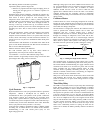
3. Remove any capacitor that shows signs of bulging, dents, or
leaking. Do not apply power to a defective capacitor as it
may explode.
Sometimes under adverse conditions, a standard run capacitor in a
system is inadequate to start compressor. In these instances, a start
assist device is used to provide an extra starting boost to
compressor motor. This device is called a positive temperature
coefficient (PTC) or start thermistor. It is a resistor wired in parallel
with the run capacitor. As current flows through the PTC at
start--up, it heats up. As PTC heats up, its resistance increases
greatly until it effectively lowers the current through itself to an
extremely low value. This, in effect, removes the PTC from the
circuit.
After system shutdown, resistor cools and resistance value returns
to normal until next time system starts. Thermistor device is
adequate for most conditions, however, in systems where off cycle
is short, device cannot fully cool and becomes less effective as a
start device. It is an easy device to troubleshoot. Shut off all power
to system.
Check thermistor with ohmmeter as described below. Shut off all
power to unit. Remove PTC from unit. Wait at least 10 minutes for
PTC to cool to ambient temperature.
Measure resistance of PTC with ohmmeter.
The cold resistance (RT) of any PTC device should be
approximately 100--180 percent of device ohm rating.
12.5--ohm PTC = 12.5--22.5 ohm resistance (beige color)
If PTC resistance is appreciably less than rating or more than 200
percent higher than rating, device is defective.
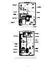
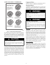
A94006
Fig. 6 – Capacitors
Cycle Protector
Bryant thermostats haveanti--cycle protection built in to protect the
compressor. Should a non--Bryant stat be utilized, it is
recommended to add a cycle protector to the system. Solid--state
cycle protector protects unit compressor by preventing short
cycling. After a system shutdown, cycle protector provides for a 5
± 2--minute delay before compressor restarts. On normal start--up, a
5--minute delay occurs before thermostat closes. After thermostat
closes, cycle protector device provides a 3--sec delay.
Cycle protector is simple to troubleshoot. Only a voltmeter capable
of reading 24v is needed. Device is in control circuit, therefore,
troubleshooting is safe with control power (24v) on and
high--voltage power off.
With high--voltage power off, attach voltmeter leads across T1 and
T3, and set thermostat so that Y terminal is energized. Make sure
all protective devices in series with Y terminal are closed.
Voltmeter should read 24v across T1 and T3. With 24v still
applied, move voltmeter leads to T2 and T3. After 5 ± 2 minutes,
voltmeter should read 24v, indicating control is functioning
normally. If no time delay isencountered or device never times out,
change control.
Crankcase Heater
Crankcase heater is a device for keeping compressor oil warm. By
keeping oil warm, refrigerant does not migrate to and condense in
compressor shell when thecompressor is off. This prevents flooded
starts which can damage compressor.
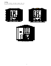
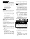
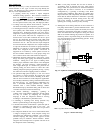
On units that have a single--pole contactor, the crankcase heater is
wired in parallel with contactor contacts and in series with
compressor. (See Fig. 7.) When contacts open, a circuit is
completed from line side of contactor, through crankcase heater,
through run windings of compressor, and to other side of line.
When contacts are closed, there is no circuit through crankcase
heater because both leads are connected to same side of line. This
allows heater to operate when system is not calling for cooling.
The heater does not operate when system is calling for cooling.
TEMPSWITCH
BLK
2111
BLKBLKBLK
CRANKCASE HTR
A97586
Fig. 7 – Wiring for Single--Pole Contactor
The crankcase heater is powered by high--voltage power of unit.
Use extreme caution troubleshooting this device with power on.
The easiest method of troubleshooting is to apply voltmeter across
crankcase heater leads to see if heater has power. Do not touch
heater. Carefully feel area around crankcase heater. If warm,
crankcase heater is probably functioning. Do not rely on this
method as absolute evidence heater is functioning. If compressor
has been running, the area will still be warm.
With power off and heater leads disconnected, check across leads
with ohmmeter. Do not look for a specific resistance reading.
Check for resistance or an open circuit. Change heater if an open
circuit is detected.
Time--Delay Relay
The TDR is a solid--state control, recycle delay timer which keeps
indoor blower operating for 90 sec after thermostat is satisfied.
This delay enables blower to remove residual cooling in coil after
compression shutdown, thereby improving efficiency of system.
The sequence of operation is that on closure of wall thermostat and
at end of a fixed on delay of 1 sec, fan relay is energized. When
thermostat is satisfied, an off delay is initiated. When fixed delay of
90 ± 20 sec is completed, fan relay is de--energized and fan motor
stops. If wall thermostat closes during this delay, TDR is reset and
fan relay remains energized. TDR is a 24v device that operates
within a range of 15v to 30v and draws about 0.5 amps. If the
blower runs continuously instead of cycling off when the fan
switch is set to AUTO, the TDR is probably defective and must be
replaced.