


50
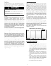
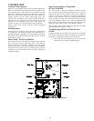
CONTROL BOX
Contactor And Capacitor
Removal of the information plate exposes the control components.
Both air conditioner and heat pump control boxes will appear to be
nearly identical. There are two contactors, two capacitors, a control
board and a compressor start assist. The contactors are identical to
those used in the standard single speed units. One controls low
capacity operation and the second controls high speed. The
capacitors also are similar to those used in standard single speed
units. You have a fan capacitor for the outdoor fan motor, and a run
capacitor for the compressor motor. The control board, start
capacitor, and start relay control the starting of the compressor.
Always replace these devices with the Factory Approved
Components.
Incoming Power
Incoming power is attached to the two power wire stripped leads.
A ground lug is also provided. Outdoor unit should always be
grounded through the ground lug to the unit disconnect and from
the disconnect to the electrical fuse box. Failure to do so can cause
serious injury or death.
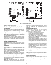
Start Circuit -- 187ANA & 286ANA
These models use the same Bristol TS reciprocating compressor
that was used in previous 2--stage Puron units. A start circuit is
needed so that the reciprocating compressor will start against
elevated head pressure. The start circuit these units use is different
from previous units. The start relay is a normally open type, and is
controlled by the circuit board instead of directly sensing the
compressor voltage.
Start Circuit Sequence of Operation --
187ANA & 286ANA
On a call for high-- or low--stage compressor operation, the start
relay is closed by the control board through the Vs, Vr, and L2
terminals. This puts the start capacitor in the circuit. Compressor
voltage is sensed on the VR and VS terminals throughout the
process. As the compressor comes up to speed, the control board
senses the change in voltage acrossVR and VS, and opens the start
relay at the appropriate voltage. The control is programmed with
the parameters for opening the start circuit. The voltage will be
different for high-- and low--stage, and for different unit sizes.
Since the same control board is used in all 2--stage units, the model
plug determines the start circuit voltage.
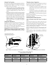
Troubleshooting 187ANA & 286ANA Start
Circuit:
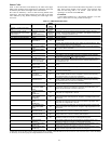
If starting problems are encountered, the control board will flash
fault codes to help indicate where the problem was encountered.
See Table 17 for appropriate actions by active fault code.
S First check that the model plug is correct for the unit
model and size, and that it is installed properly
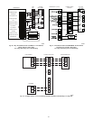
Fig. 35 – Preferred and Evolution Series Control Box Identification