


12
ELECTRICAL
ELECTRICAL SHOCK HAZARD
Failure to follow this warning could result in personal injury
or death.
Exercise extreme caution when working on any electrical
components. Shut off all power to system prior to
troubleshooting. Some troubleshooting techniques require
power to remain on. In these instances, exercise extreme
caution to avoid danger of electrical shock. ONLY TRAINED
SERVICE PERSONNEL SHOULD PERFORM
ELECTRICAL TROUBLESHOOTING.
!
WARNING
Aluminum Wire
UNIT OPERATION AND SAFETY HAZARD
Failure to follow this caution may result in equipment
damage or improper operation.
Aluminum wire may be used in the branch circuit (such as
the circuit between the main and unit disconnect), but only
copper wire may be used between the unit disconnect and the
unit.
CAUTION
!
Whenever aluminum wire is used in branch circuit wiring with this
unit, adhere to the following recommendations.
Connections must be made in accordance with the National
Electrical Code (NEC), using connectors approved for aluminum
wire. The connectors must be UL approved (marked Al/Cu with
the UL symbol) for the application and wire size. The wire size
selected must have a current capacity not less than that of the
copper wire specified, and must not create a voltage drop between
service panel and unit in excess of 2 of unit rated voltage. To
prepare wire before installing connector, all aluminum wire must
be “brush--scratched” and coated with a corrosion inhibitor such as
Pentrox A. When it is suspected that connection will be exposed to
moisture, it is very important to cover entire connection completely
to prevent an electrochemical action that will cause connection to
fail very quickly. Do not reduce effective size of wire, such as
cutting off strands so that wire will fit a connector. Proper size
connectors should be used. Check all factory and field electrical
connections for tightness. This should also be done after unit has
reached operating temperatures, especially if aluminum conductors
are used.
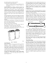
Contactor
The contactor provides a means of applying power to unit using
low voltage (24v) from transformer in order to power contactor
coil. Depending on unit model, you may encounter single-- or
double--pole contactors. Exercise extreme caution when
troubleshooting as 1 side ofline may be electrically energized. The
contactor coil is powered by 24vac. If contactor does not operate:
1. With power off, check whether contacts are free to move.
Check for severe burning or arcing on contact points.
2. With power off, use ohmmeter to check for continuity of
coil. Disconnect leads before checking. A low resistance
reading is normal. Do not look for a specific value, as
different part numbers will have different resistance values.
3. Reconnect leads and apply low--voltage power to contactor
coil. This may be done by leaving high--voltage power to
outdoor unit off and turning thermostat to cooling. Check
voltage at coil with voltmeter. Reading should be between
20v and 30v. Contactor should pull in if voltage is correct
and coil is good. If contactor does not pull in, replace
contactor.
4. With high--voltage power off and contacts pulled in, check
for continuity across contacts with ohmmeter. A very low or
0 resistance should be read. Higher readings could indicate
burned or pitted contacts which may cause future failures.
Capacitor
ELECTRICAL SHOCK HAZARD
Failure to follow this warning could result in personal injury
or equipment damage.
Capacitors can store electrical energy when power is off.
Electrical shock can result if you touch the capacitor terminals
and discharge the stored energy. Exercise extreme caution
when working near capacitors. With power off, discharge
stored energy by shorting across the capacitor terminals with a
15,000--ohm, 2--watt resistor.
!
WARNING
NOTE: If bleed resistor is wired across start capacitor, it must be
disconnected to avoid erroneous readings when ohmmeter is
applied across capacitor.
ELECTRICAL SHOCK HAZARD
Failure to follow this warning could result in personal injury
or equipment damage.
Always check capacitors with power off. Attempting to
troubleshoot a capacitor with power on can be dangerous.
Defective capacitors may explode when power is applied.
Insulating fluid inside is combustible and may ignite, causing
burns.
!
WARNING
Capacitors are used as a phase--shifting device to aid in starting
certain single--phase motors. Check capacitors as follows:
1. With power off, discharge capacitors as outlined above.
Disconnect capacitor from circuit. Put ohmmeter on R X
10k scale. Using an analog ohmmeter, check each terminal
to ground (use capacitor case). Discard any capacitor which
measures 1/2 scale deflection or less. Place ohmmeter leads
across capacitor and place on R X 10k scale. Meter should
jump to a low resistance value and slowly climb to higher
value. Failure of meter to do this indicates an open
capacitor. If resistance stays at 0 or a low value, capacitor is
internally shorted.
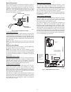
2. Capacitance testers are available which will read value of
capacitor. If value is not within ±10 percent value stated on
capacitor, it should be replaced. If capacitor is not open or
shorted, the capacitance value is calculated by measuring
voltage across capacitor and current it draws.
ELECTRICAL SHOCK HAZARD
Failure to follow this warning could result in personal injury
or death.
Exercise extreme caution when taking readings while power is
on.
!
WARNING