


46
S The ODF fan delay defeat can be toggled by shorting the
forced defrost pins for >15 seconds while in the standby
mode (status LED on solid). The LED will start to flash
when the toggle has taken place.
S Status code 4 shows the fan delay defeat is active (no
delay)
S Status code 3 shows that it is not active (20 second
delay)
The code will continue to be displayed until after the short is
removed. Once the short is removed, there is a 5 second wait
before the code is cancelled. The code that is flashing will finish
before going back to sold LED. the control is shipped with the
ODF fan delay defeat NOT active. the change in status is
remembered until toggled to a new status. A power down / power
up sequence will not reset the status. It may be necessary to do the
toggle twice to cycle to the desired state of defeat.
Defrost
Hold
in a non--communicating system, if the thermostat becomes
satisfied (Y1 or Y1 and Y2) before the defrost cycle is terminated,
the control will “hold” in defrost mode and finish the defrost cycle
on the next call for heat.
With communicating Evolution Control, defrost hold is not needed
in a communicating system because the User Interface will
complete the defrost cycle before shutting down the system.
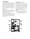
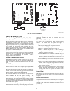
Forced Defr
ost
With non--communicating (non--Evolution) control, forced defrost
can be initiated by manually shorting the 2--pin header labeled
FORCED DEFROST (see Fig 43) on the control board for 5
seconds then releasing.
With communicating (Evolution) control, forced defrost is initiated
with the User Interface.
On all models, during a Forced Defrost:
S If coil temperature is at defrost temperature of 32_F, and
outdoor air temperature is below 50_F, a full defrost
sequence will occur.
S If coil temperature or outdoor air temperature does not
meet the above requirements, an abbreviated 30 second
defrost will occur.
Quiet Shift
Quiet Shift is a field--selectable defrost mode which may eliminate
occasional noise that could be heard at the start of the defrost cycle
and restarting of the heating cycle. On models with a
non--communicating system, this feature must be enabled by
selecting the 3rd position of the 3--position dip switch. For models
with communicating (Evolution) systems, it must be enabled at the
User Interface. When activated, the following sequence of
operation will occur. Reversing valve will energize and
compressor will turn off for 30 seconds, then turn back on to
complete defrost. At the end of the defrost cycle, the reversing
valve de--energizes, compressor will turn off for another 30
seconds, and the fan will turn off for 40 seconds, before starting in
the heating mode.
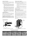
Liquid--Line Solenoid Accessory
In heat pump long--line applications, a liquid--line solenoid is
required to control refrigerant migration in the heating mode. The
solenoid should be installed near the outdoor unit with the arrow
facing the outdoor unit. This is the direction of flow control. See
application manual for long--line application details.
Accessory Liquid Solenoid with Evolution
Communicating
Control:
When using the Evolution Control, the liquid--line solenoid output
is provided at the Y1 connection. Connect the solenoid as shown in
the wiring label diagram. This is a 24vac output that is energized
whenever the compressor is energized. It closes, in the compressor
off mode, to prevent refrigerant migration into the unit through the
liquid--line.
On Models with Accessory Liquid Solenoid Using
a
Non--Communicating
Thermostat:
The liquid solenoid is connect to the Y1 and C terminal
connections. The liquid solenoid closes, in the compressor off
mode, to prevent refrigerant migration into the unit through the
liquid--line.
CHECK CHARGE
All 286A units must be charged in high stage only.
Factory charge amount and desired subcooling are shown on unit
rating plate. Charging method is shown on information plate inside
unit. To properly check or adjust charge, conditions must be
favorable for subcooling charging. Favorable conditions exist
when the outdoor temperature is between 70_F and 100_F
(21.11_C and 37.78_C), and the indoor temperature is between
70_F and 80_F (21.11_C and 26.67_C). Follow the procedure
below:
Unit is factory charged for 15ft (4.57 m) of lineset. Adjust charge
by adding or removing 0.6 oz/ft of 3/8 liquid line above or below
15ft (4.57 m) respectively.
For standard refrigerant line lengths (80 ft/24.38 m or less), allow
system to operatein cooling mode at least 15 minutes. If conditions
are favorable, check system charge by subcooling method. If any
adjustment is necessary, adjust charge slowly and allow system to
operate for 15 minutes to stabilize before declaring a properly
charged system.
If the indoor temperature is above 80_F (26.67_C), and the
outdoor temperature is in the favorable range, adjust system charge
by weight based on line length and allow the indoor temperature to
drop to 80_F (26.67_C) before attempting to check system charge
by subcooling method as described above.
If the indoor temperature is below 70_F (21.11_C), or the outdoor
temperature is not in the favorable range, adjust charge for line set
length above orbelow 15ft (4.57 m) only. Charge level should then
be appropriate for the system to achieve rated capacity. The charge
level could then be checked at another time when the both indoor
and outdoor temperatures are in a more favorable range.
NOTE: If line length is beyond 80 ft (24.38 m) or greater than 20
ft (6.10 m) vertical separation, See Long Line Guideline for
special charging requirements.
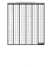
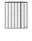
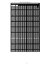
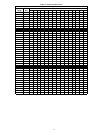
Heating Check Chart Procedure
To check system operation during heating cycle, refer to the Heat
Pump Charging Instructions label on outdoor unit. This chart
indicates whether a correct relationship exists between system
operating pressure and air temperature entering indoor and outdoor
units. If pressure and temperature do not match on chart, system
refrigerant charge may not be correct. Do not use chart to adjust
refrigerant charge.
NOTE: In heating mode, check refrigerant charge only when
pressures are stable. If in doubt, remove charge and weigh in
correct refrigerant charge.
NOTE: When charging is necessary during heating season, charge
must be weighed in accordance with unit rating plate, ±0.6 oz./ft.
of 3/8--in. liquid--line above or below 15 ft., respectively.
EXAMPLE:
To calculate additional charge required for a 25--ft. line set:
25 ft. -- 15 ft. = 10 ft. X 0.6 oz./ft. = 6 oz. of additional charge.