


54
Status Codes
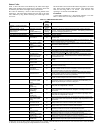
Table 17 shows the status codes flashed by the amber status light.
Most system problems can be diagnosed by reading the statuscode
as flashed by the amber status light on the control board.
The codes are flashed by a series of short and long flashes of the
status light. The short flashes indicate the first digit in the status
code, followed by long flashes indicating the second digit of the
error code.
The short flash is 0.25 seconds ON and the long flash is 1.0 second
ON. Time between flashes is 0.25 seconds. Time between short
flash and first long flash is 1.0 second. Time between code
repeating is 2.5 seconds with LED OFF.
EXAMPLE:
3 short flashes followed by 2 long flashes indicates a 32 code.
Table 17 shows this to be low pressure switch open.
Table 17—TROUBLESHOOTING
OPERATION
FAULT
AMBER
LED FLASH
CODE
POSSIBLE CAUSE AND ACTION
Standby – no call for unit opera-
tion
None
On solid,
no flash
Normal operation
Emergency Mode --- Model
288A/180ANAwith serial nu m ber
3709 and prior.
StandardTh ermostat
Control
(288A/180ANAonly)
Rapid,
continuous
flashing
Unitbeingcontrolledby standard thermostat inputsinsteadof Evolution
Control. Only high stage operation isavailable. This operating mode should
beusedin emergency situationsonly.
Low Stage Cool/HeatOperation None 1, pause Normal operation
High Stage Cool/Heat Operation None 2, pause Normal operation
System Communica-
tions Failure
16
Communication with User Interface lost. Check wiring to UI, indoor and
outdoor units
Invalid Model P lug 25
Control does not detect a model plug or detects an invalid model plug. Unit
will notoperate withoutcorrect model plug.
High Pressure S witch
Open
31*
High---pressureswitch trip. Check refrigerantcharge,outdoorfan operation
and coilsfor airflowrestrictions.
Low Pressure Switch
Open
32* Low---pressure switch trip. Check refrigerant charge and indoor air flow.
Control Fault 45 Outdoor unit control board has failed. Control board needs to be replaced.
Brown Out (230v) 46
Line voltage < 187vfor a t least 4 seconds. Compressor and fan operation
notalloweduntilvoltage>
190v. Verify line voltage.
No 230v at Unit
Measuredat L1 and
L2 oncircuitboard
47
There is no 230v atthe contactor when indoor unit ispowered and cooling/
heating demand exists. Verify the disconnect isclosed and 230v wiringis
connectedtothe unit.
Outdoor Air Temp
Sensor Fault
53
Outdoor air sensor not reading or out of range.Ohm out sensor and check
wiring.
Outdoor Coil
Sensor Fault
55 Coilsensor notreadingor outof range.Ohm outsensor andcheck wiring.
Thermistors out of
range
56
Improper relationship between coil sensor and outdoor air sensor. Ohm out
sensorsand checkwiring.
LowStage
Thermal Cutout
71*
Compressor operation detected then disappears while low stage demand
exists. Possiblecausesare internal compressor overloadtripor startrelay
andcapacitor heldin circuittoo long (ifinstalled).
High Stage
Thermal Cutout
72*
Compressor operation detected then disappears while high stage demand
exists. Possiblecausesare internal compressor overloadtripor startrelay
andcapacitor heldin circuittoo long (ifinstalled).
Contactor Shorted 73*
Compressor v oltage sensed when no demand for compressor operation
exists. Contactor may be stuck closed or there is a wiring error.
No 230V at
Compressor (288A
Only)
74
Compressor voltagenot sensedwhen compressor shouldbestarting.Con-
tactor may be stuck open or there is a wi ring error.
LowStageDidNot
Start
(286A Only)
75
Specified startvoltage at VRterminal wasnot achieved in low stage. Start
relay was de---ener gized after 1second.
LowStageDidNot
Start 3times
(286AOnly)
76
For 3 consecutive low stage starts, the specified start voltage at VR terminal
was notachieved & start relay wasde---en er gized. Low stagel ocked out for
30minutes.
High Stage Did Not
Start
(286A Only)
77
Specified start voltage at VS terminal w as not achieved in high stage. Start
relay was de---ener gized after 1second.
High Stage Did Not
Start 3 times (286A
Only)
78
For 3 consecutive high stage starts, t he specified start voltage at VS t erminal
was notachieved & start relay was de---energized. High stagel ocked out for
30minutes.
LowStage
Thermal Lockout
81
Thermal cutout occurs in three consecutive low/high stage cycles. Low
stage lockedout for 4 hoursor until 24vpowerrecycled.
High Stage
Thermal Lockout
82
Thermal cutout occurs in three consecutive high/low stage cycles. High
stage lockedout for 4 hoursor until 24vpowerrecycled.
Low---PressureLock-
out
83
Low pressure switch trip has occurred during 3 consecutive cycles. Unit
operation lockedout for4 hoursor until 24v power recycled.
High---Pressure
Lockout
84
High pressure switch trip has occurred during 3 consecutive cycles. Unit
operation lockedout for4 hoursor until 24v power recycled.
LowContactorOpen
(286A Only)
85
Compressor v oltage not sensed when compressor should be starting. Low
stage contactor may bestuck open or there isa wiring error.
High Contactor Open
(286A Only)
87
Compressor v oltage not sensed when compressor should be starting. High
stage contactor may bestuck open or there isa wiring error.
*Sequence: Compressor contactor is de---energized and outdoor fan is energized f or up to 15 minutes. If demand still exists, control will energize compressor
contactor after 15 minutedelay. Iffault iscleared, unitwillresumeoperation. Iffault still exists, fan shutsoff, anderror code continuesto flash.Control will attempt
re---start every 15 minutes. Cycling low voltage defeats the 15 minute delay.