


59
SYSTEM FUNCTIONS AND
SEQUENCE OF OPERATION
The outdoor unit control system has special functions. The
following is an overview of the two--stage control functions:
Cooling and Heating Operation
The 286B/187B/289B/180B model utilizes either a standard
2--stage indoor thermostat or Evolution Communication User
Interface. With a call for first stage cooling, the outdoor fan,
reversing valve, and low stage compressor are energized. If
low--stage cannot satisfy cooling demand, high--stage cooling is
energized by the second stage of indoor thermostat or User
Interface. After second stage is satisfied, the unit returns to
low--stage operation until first stage is satisfied or until second
stage is required again. When both first stage and second stage
cooling are satisfied, the compressor will shut off. The reversing
valve will remain energized until the control board power is
removed or a call for heating in initiated. With a call for heating,
the outdoor fan and compressor are energized. The compressor will
operate in high or low stage operation, as needed to meet the
heating demand. When the heating demand is satisfied, the
compressor and fan will shut off. The reversing valve is
de--energized in the heating mode.
NOTE: When two--stage unit is operating at low--stage, system
vapor (suction) pressure will be higher than a standard single--stage
system or high--stage operation.
NOTE: Outdoor fan motor will continue to operate for one minute
after compressor shuts off, when outdoor ambient is greater than or
equal to 100°F. This reduces pressure differential for easier starting
on next cycle.
NOTE: If unit has not operated within the past 12 hours, or
following a unit power--up, upon the next thermostat high-- or
low--stage demand, unit operates for a minimum of 5 minutes in
high--stage.
On models with non--communicating (non--Evolution) systems,
with first stage of cooling, Y1 and O are powered on; and with
second stage of cooling, Y1, Y2, and O are on. For these systems,
with first stage of heating Y1 is on and for second stage of heating,
Y1 and Y2 are on. When the reversing valve is energized, O is
powered on.
Communication and Status Function Lights For
Evolution Control only, Green communications
(COMM) Light
A green LED (COMM light) on the outdoor board indicates
successful communication with the other system products. The
green LED will remain OFF until communication is established.
Once a valid command is received, the green LED will turn ON
continuously. If no communication is received within 2 minutes,
the LED will be turned OFF until the next valid communication.
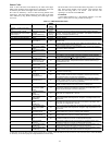
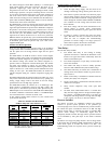
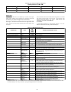
Amber Status
Light
An amber colored STATUS light is used to display the operation
mode and fault codes as specified in the troubleshooting section.
See Table 21 for codes and definitions.
NOTE: Only one code will be displayed on the outdoor unit
control board (the most recent, with the highest priority).
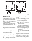
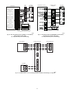
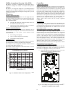
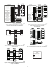
Utility Interface With Evolution Control
The utility curtailment relay should be wired between R and Y2
connections on the control board for Evolution Communicating
Systems only (see Fig. 49.) This input allowsa power utility device
to interrupt compressor operation during peak load periods. When
the utility sends a signal to shut the system down, the User
Interface will display, “Curtailment Active”.
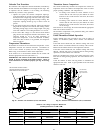
Compressor Operation on 289B/180B Models:
The basic scroll design has been modified with the addition of an
internal unloading mechanism that opens a bypass port in the first
compression pocket, effectively reducing the displacement of the
scroll. The opening and closing of the bypass port is controlled by
an internal electrically operated solenoid.
The modulated scroll uses a single step of unloading to go from
full capacity to approximately 67% capacity. A single speed, high
efficiency motor continues to run while the scroll modulates
between the two capacity steps. Modulation is achieved by venting
a portion of the gas in the first suction pocket back to the low side
of the compressor, thereby reducing the effective displacement of
the compressor. Full capacity is achieved by blocking these vents,
thus increasing the displacement to 100%. A DC solenoid in the
compressor controlled by a rectified 24 volt AC signal in the
external solenoid plug moves the slider ring that covers and
uncovers these vents. The vent covers are arranged in such a
manner that the compressor operates at approximately 67%
capacity when the solenoid is not energized and 100% capacity
when the solenoid is energized.
The loading and unloading of the two step scroll is done “on the
fly” without shutting off the motor between steps.
NOTE: 67% compressor capacity translates to approximately 80%
cooling or heating capacity at the indoor coil. The compressor will
always start unloaded and stay unloaded for five seconds even
when the thermostat is calling for high stage.
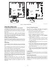
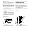
Fan Motor
Fan motor rotates the fan blade that either draws or blows air
through outdoor coil to exchange heat between refrigerant and air.
Motors are totally enclosed to increase reliability. This also
eliminates need for rain shield.
ELECTRICAL SHOCK HAZARD
Failure to follow this warning could result in personal injury
or death.
Turn off all power to unit before servicing or replacing fan
motor. Be sure unit main power switch is turned off.
!
WARNING
The bearings are permanently lubricated; therefore, no oil ports are
provided.
For suspected electrical failures, check for loose or faulty electrical
connections, or defective fan--motor capacitor. Fan motor is
equipped with thermal overload device in motor windings which
may open under adverse operating conditions. Allow time for
motor to cool so device can reset. Further checking of motor can be
done with an ohmmeter. Set scale on R X 1 position; check for
continuity between three leads. Replace motors that show an open
circuit in any of the windings. Place 1 lead of ohmmeter on each
motor lead. At same time, place other ohmmeter lead on motor case
(ground). Replace any motor that shows resistance to ground, signs
of arcing, burning, or overheating.
Located above the compressor is a single--speed fan motor and fan.
The 180B/289B air conditioner and heat pump models use the
ECM variable speed fan motor.