


68
SYSTEM FUNCTION AND SEQUENCE
OF OPERATION
NOTE: Defrost control board is equipped with 5 minute lockout
timer that is initiated upon any interruption of power.
Turn on power to indoor and outdoor units. Transformer is
energized.
Cooling
On a call for cooling, thermostat makes circuits R--O, R--Y, and
R--G. Circuit R--O energizes reversing valve, switching it to
cooling position. Circuit R--Y sends low voltage through the
safeties and energizes the T1 terminal on the circuit board. If the
compressor has been off for 5 minutes, or power has not been
cycled for 5 minutes, the OF2 relay and T2 terminal will energize.
This will close the contactor, and start the outdoor fan motor and
compressor.
When the cycle is complete, R--Y is turned off, stopping the
compressor and outdoor fan. The 5 minute time guard begins
counting. Compressor will not come on again until this delay
expires. In the event of a power interruption, the time guard will
not allow another cycle for 5 minutes.
NOTE: If the indoor blower off delay is enabled, it will run up to
an additional 90 seconds to increase system efficiency.
Heating
On a call for heating, thermostat makes circuits R--Y and R--G.
Circuit R--Y sends low voltage through the safeties and energizes
the T1 terminal on the circuit board. T1 energizes the defrost logic
circuit. If the compressor has been off for 5 minutes, or power
has not been cycled for 5 minutes, the OF2 relay and T2 terminal
will energize. This will close the contactor, start the outdoor fan
motor and compressor.
When the cycle is complete, R--Y is turned off , stopping the
compressor and outdoor fan. The 5 minute time guard begins
counting. Compressor will not come on again until this time delay
expires. In the event of a power interruption, the time guard will
not allow another cycle for 5 minutes.
Compressor Operation
The basic scroll design has been modified with the addition of an
internal unloading mechanism that opens a by--pass port in thefirst
compression pocket, effectively reducing the displacement of the
scroll. The opening and closing of the by--pass port is controlled
by an internal electrically operated solenoid. The modulated scroll
uses a single step of unloading to go from full capacity to
approximately 67% capacity.
A single speed, high efficiency motor continues to run while the
scroll modulates between the two capacity steps. Modulation is
achieved by venting a portion of the gas in the first suction pocket
back to the low side of the compressor, thereby reducing the
effective displacement of the compressor.
Full capacity is achieved by blocking these vents, thus increasing
the displacement to 100%. A DC solenoid in the compressor
controlled by a rectified 24 volt AC signal in the external solenoid
plug moves the slider ring that covers and uncovers these vents.
The vent covers are arranged in such a manner that the compressor
operates at approximately 67% capacity when the solenoid is not
energized and 100% capacity when the solenoid is energized. The
loading and unloading of the two step scroll is done ”on the fly”
without shutting off the motor between steps.
NOTE: 67% compressor capacity translates to approximately 75%
cooling or heating capacity at the indoor coil.
The compressor will always start unloaded and stay unloaded for
five seconds even when the thermostat is calling for high stage
capacity.
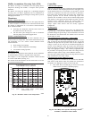
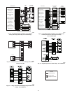
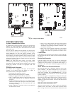
Quiet Shift
Quiet shift is a field selectable defrost mode (factory set to OFF),
which will eliminate occasional noise that could be heard at the
start of defrost cycle and restarting of heating cycle. It is selected
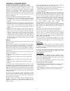
by placing DIP switch 3 on defrost board (see Fig. 53) in the ON
position.
When Quiet Shift switch is placed in ON position, and a defrost is
initiated, the following sequence of operation will occur. Reversing
valve will energize, compressor will turn off for 30 seconds, and
then turn back on to complete defrost. At the start of heating after
conclusion of defrost, reversing valve will de--energize,
compressor will turn off for another 30 seconds, and the fan will
turn off for 40 seconds, before starting in the heating mode.
Defrost
The defrost control is a time/temperature control which has field
selectable settings of 30, 60, 90, or 120 minutes, factory set to 90
minutes. These settings represent the amount of time that must pass
after closure of the defrost thermostat before the defrost sequence
begins.
The defrost thermostat senses coil temperature throughout the
heating cycle. When the coil temperature reaches the defrost
thermostat setting of approximately 32_F(0_C), it will close,
which energizes the DFT terminal and begins the defrost timing
sequence. When the DFT has been energized for the selected time,
the defrost cycle begins. Defrost cycle is terminated when defrost
thermostat opens, or automatically after 10 minutes.
Defrost Speedup
To initiate a forced defrost, speedup pins (J1) must be shorted with
a flat head screwdriver for 5 seconds and RELEASED.Ifthe
defrost thermostat is open, a short defrost cycle will be observed
(actual length depends on Quiet Shift switch position). When Quiet
Shift is off, only a short 30 second defrost cycle is observed. With
Quiet Shift ON, the speedup sequence is one minute; 30 second
compressor off period followed by 30 seconds of defrost with
compressor operation. When returning to heating mode, the
compressor will turn off for an additional 30 seconds and the fan
for 40 seconds.
If the defrost thermostat is closed, a complete defrost cycle is
initiated. If the Quiet Shift switch is turned on, the compressor will
be turned off for two 30 second intervals as explained previously.
OF2
HK32EA003
O
F1
ON
QUIET
SHIFT
120
30
60
60
30
90
INTERVAL TIMER
OFF
P3
DFT
O R W
2
Y C
T2 C C O
DFT
T1 Y
P1
J1
SPEEDUP
Speedup
Pins
Defrost interval
DIP switches
Quiet
Shift
A05378
Fig. 53 – Defrost Control