


24
Service Valves and Pumpdown
PERSONAL INJURY AND UNIT DAMAGE HAZARD
Failure to follow this warning could result in personal injury
or equipment damage.
Never attempt to make repairs to existing service valves. Unit
operates under high pressure. Damaged seats and o--rings
should not be replaced. Replacement of entire service valve is
required. Service valve must be replaced by properly trained
service technician.
!
WARNING
Service valves provide a means for holding original factory charge
in outdoor unit prior to hookup to indoor coil. They also contain
gauge ports for measuring system pressures and provide shutoff
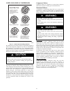
convenience for certain types of repairs. (See Fig. 15 and Fig. 16.)
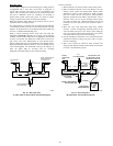
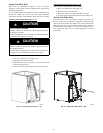
Two types of service valves are used in outdoor residential
equipment. The first type is a front--seating valve, which has a
service port that contains a Schrader fitting. The service port is
always pressurized after the valve is moved off the front--seat
position.
The second type is a combination front--seating/back--seating
valve, which has a metal--to--metal seat in both the open and closed
positions. When it is fully back--seated (will no longer turn counter
clockwise), the service port is not
pressurized. To pressurize the
service port, this valve must be moved off the back--seating
position (turned clockwise slightly). The gage port in this valve
does not contain a Schrader fitting. Both types of service valves are
designed for sweat connection to the field tubing.
The service valves in the outdoor unit come from the factory
front--seated. This means that the refrigerant charge is isolated from
the line--set connection ports. All heat pumps are shipped with an
adapter stub tube. This tube must be installed on the liquid service
valve. After connecting the stub tube to the liquid service valve of
a heat pump, the valves are ready for brazing. The interconnecting
tubing (line set) can be brazed to the service valves using industry
accepted methods and materials. Consult local codes.
Before brazing the line set to the valves, the belled ends of the
sweat connections on the service valves must be cleaned so that no
brass plating remains on either the inside or outside of the bell
joint. To prevent damage to the valve and/or cap “O” ring, use a
wet cloth or other acceptable heat--sinking material on the valve
before brazing. To prevent damage to the unit, use a metal barrier
between brazing area and unit.
After the brazing operation and the refrigerant tubing and
evaporator coil have been evacuated, the valve stem can be turned
counterclockwise until back--seats, which releases refrigerant into
tubing and evaporator coil. The system can now be operated.
Back--seating service valves must be back--seated (turned
counterclockwise until seated) before the service--port caps can be
removed and hoses of gauge manifold connected. In this position,
refrigerant has access from and through outdoor and indoor unit.
The service valve--stem cap is tightened to 20 ± 2 ft/lb torque and
the service--port caps to 9 ± 2 ft/lb torque. The seating surface of
the valve stem has a knife--set edge against which the caps are
tightened to attain a metal--to--metal seal. If accessory pressure
switches are used, the service valve must be cracked. Then, the
knife--set stem cap becomes the primary seal.
The service valve cannot be field repaired; therefore, only a
complete valve or valve stem and service--port caps are available
for replacement.
If the service valve is to be replaced, a metal barrier must be
inserted between the valve and the unit to prevent damaging the
unit exterior from the heat of the brazing operations.
PERSONAL INJURY HAZARD
Failure to follow this caution may result in personal injury.
Wear safety glasses, protective clothing, and gloves when
handling refrigerant.
CAUTION
!
Pumpdown Procedure
Service valves provide a convenient shutoff valve useful for certain
refrigeration--system repairs. System may be pumped down to
make repairs on low side without losing complete refrigerant
charge.
1. Attach pressure gauge to suction service--valve gauge port.
2. Front seat liquid--line valve.
3. Start unit in cooling mode. Run until suction pressure
reaches 5 psig (35kPa). Do not allow compressor to pump
to a vacuum.
4. Shut unit off. Front seat suction valve.
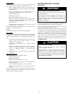
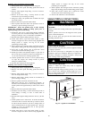
FIELD SIDE
STAINLESS
STEEL
STEM
SERVICE
PORT
ENTRANCE
BACK
SEAT
POSITION
FRONT
SEAT
POSITION
FORGED BACK SEATING VALVE
A91435
Fig. 15 – Suction Service Valve (Back Seating)
Used in Preferred and Evolution ACs and HPs.
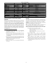
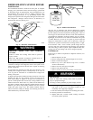
STEM
SERVICE PORT
W/SCHRADER CORE
SEAT
BAR STOCK FRONT SEATING VALVE
FIELD
SIDE
A91447
Fig. 16 – Suction Service Valve (Front Seating)
Used in Legacy RNC and Legacy Line ACs and HPs
NOTE: All outdoor unit coils will hold only factory--supplied
amount of refrigerant. Excess refrigerant, such as in long--line
applications, may cause unit to relieve pressure through internal
pressure--relief valve (indicated by sudden rise of suction pressure)
before suction pressure reaches 5 psig (35kPa). If this occurs, shut
unit off immediately, front seat suction valve, and recover
remaining pressure.