


30
Replacing TXV on an Indoor Coil
(pre--2006)
1. Pump system down to 2 psig and recover refrigerant.
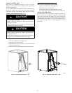
2. Remove coil access panel and fitting panel from front of
cabinet.
3. Remove TXV support clamp using a 5/16--in. nut driver.
Save the clamp.
4. Remove R--22 TXV using a backup wrench on flare
connections to prevent damage to tubing.
5. Using wire cutters, cut equalizer tube off flush with vapor
tube inside cabinet.
6. Remove bulb from vapor tube inside cabinet.
7. Braze equalizer stub--tube closed. Use protective barrier as
necessary to prevent damage to drain pan.
IMPORTANT: Route the equalizer tube of TXV through
suction line connection opening in fitting panel prior to
replacing fitting panel around tubing.
8. Install TXV with 3/8--in. copper tubing through small hole
in service panel. Use wrench and backup wrench, to avoid
damage to tubing or valve, to attach TXV to distributor.
9. Reinstall TXV support clamp (removed in item 3).
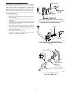
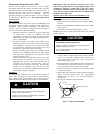
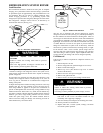
10. Attach TXV bulb to vapor tube inside cabinet, in same
location as original was when removed, using supplied bulb
clamps (nylon or copper). See Fig. 25 for correct
positioning of sensing bulb.
11. Route equalizer tube through suction connection opening
(large hole) in fitting panel and install fitting panel in place.
12. Sweat inlet of TXV, marked “IN” to liquid line. Avoid
excessive heat which could damage valve.
13. Install vapor elbow with equalizer adapter to vapor line of
line set and vapor connection to indoor coil. Adapter has a
1/4--in. male connector for attaching equalizer tube.
14. Connect equalizer tube of TXV to 1/4--in. equalizer fitting
on vapor line adapter. Use backup wrench to prevent
damage to equalizer fitting.
15. Proceed with remainder of unit installation.
Replacing TXV on Indoor Coil
(post--2006)
1. Pump system down to 2 psig and recover refrigerant.
2. Remove coil access panel and fitting panel from front of
cabinet.
3. Remove TXV support clamp using a 5/16--in. nut driver.
Save the clamp (N coils only).
4. Remove TXV using a backup wrench on connections to
prevent damage to tubing.
5. Remove equalizer tube from suction line of coil.
Note: Some coils may have a mechanical connection. If
coil has a braze connection, use file or tubing cutter to cut
brazed equalizer line approximately 2 inches above suction
tube.
6. Remove bulb from vapor tube inside cabinet.
7. Install the new TXV using a wrench and backup wrench to
avoid damage to tubing or valve to attach TXV to
distributor.
8. Reinstall TXV support clamp (removed in item 3). (N coils
only.)
9. Attach equalizer tube to suction line. If coil has mechanical
connection, then use wrench and back up wrench to attach.
If coil has brazed connection, use file or tubing cutters to
remove mechanical flare nut from equalizer line. Then use
coupling to braze the equalizer line to stub (previous
equalizer line) in suction line.
10. Attach TXV bulb to vapor tube inside cabinet, in same
location as original was when removed, using supplied bulb
clamps (nylon or copper). See Fig. 25 for correct
positioning of sensing bulb.
11. Route equalizer tube through suction connection opening
(large hole) in fitting panel and install fitting panel in place.
12. Sweat inlet of TXV, marked “IN” to liquid line. Avoid
excessive heat which could damage valve.
13. Proceed with remainder of unit installation.
MAKE PIPING CONNECTIONS
!
WARNING
PERSONAL INJURY AND ENVIRONMENTAL
HAZARD
Failure to follow this warning could result in personal injury
or death.
Relieve pressure and recover all refrigerant before system
repair or final unit disposal.
Use all service ports and open all flow--control devices,
including solenoid valves.
CAUTION
!
UNIT DAMAGE HAZARD
Failure to follow this caution may result in equipment damage
or improper operation.
Do not leave system open to atmosphere any longer than
minimum required for installation. POE oil in compressor is
extremely susceptible to moisture absorption. Always keep
ends of tubing sealed during installation.
CAUTION
!
UNIT DAMAGE HAZARD
Failure to follow this caution may result in equipment
damage or improper operation.
If ANY refrigerant tubing is buried, provide a 6 in. vertical
rise at service valve. Refrigerant tubing lengths up to 36 in.
may be buried without further special consideration. Do not
bury lines longer than 36 in.
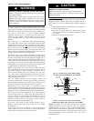
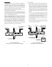
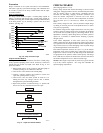
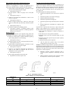
THERMOSTATIC
EXPANSION
VALVE
EQUALIZE
R
TUBE
SENSING
BULB
COIL
A91277
Fig. 26 – Typical TXV Installation