


64
Temperature Thermistors
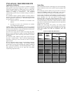
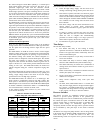
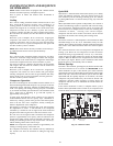
Thermistors are electronic devices which sense temperature. As the
temperature increases, the resistance decreases. Thermistors are
used to sense outdoor air (OAT) and coil temperature (OCT).
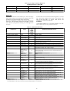
Refer to Fig. 43 for resistance values versus temperature.
If the outdoor air or coil thermistor should fail, the control will
flash the appropriate fault code. (See Table 21.)
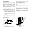
IMPORTANT: The outdoor air thermistor and coil thermistor
should be factory mounted in the final locations. Check to
ensure thermistors are mounted properly per Fig. 46 and Fig.
47.
Thermistor Sensor Comparison
The control continuously monitors and compares the outdoor air
temperature sensor and outdoor coil temperature sensor to ensure
proper operating conditions. The comparison is:
S In cooling if the outdoor air sensor indicates ≥ 10_F
warmer than the coil sensor (or) the outdoor air sensor
indicates ≥ 20_F cooler than the coil sensor, the sensors
are out of range.
S In heating if the outdoor air sensor indicates ≥ 35_F
warmer than the coil sensor (or) the outdoor air sensor
indicates ≥ 10_F cooler than the coil sensor, the sensors
are out of range.
If the sensors are out of range, the control will flash theappropriate
fault code as shown in Table 21.
The thermistor comparison is not performed during low ambient
cooling or defrost operation.
Failed Thermistor Default Operation
Factory defaults have been provided in the event of failure of
outdoor air thermistor (OAT) and/or outdoor coil thermistor
(OCT).
If the OAT sensor should fail, low ambient cooling will not be
allowed and the one--minute outdoor fan off delay will not occur.
Defrost will be initiated based on coil temperature and time.
If the OCT sensor should fail, low ambient cooling will not be
allowed. Defrost will occur at each time interval during heating
operation, but will terminate after 5 minutes.
If there is a thermistor out of range error, defrost will occur at each
time interval during heating operation, but will terminate after 5
minutes.
Count the number of short and long flashes to determine the
appropriate flash code. Table 21 gives possible causes and actions
related to each error.
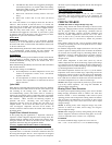
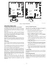
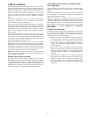
OAT Thermistormustbe locked in
placewith spherical nibend facingto-
wardsthe frontof thecontrol box
Fig. 46 – Outdoor Air Thermistor (OAT) Attachment
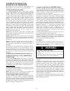
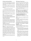
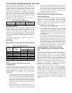
OCT Thermistor
must be secured
tight onstubtube.
Fig. 47 – Outdoor Coil Thermistor (OCT) Attachment