


70
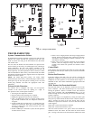
TWO STAGE COMMUNICATING 167A/266A
These units provide an Evolution capable 2 stage product in the
Preferred line utilizing 2 stage scroll technology. These units are
designed using the full--coil cabinet with is currently used for the
Legacy Line products. Although the deluxe cabinet used in other
Preferred Series products provides excellent sound levels,
serviceability and stylish appearance, its design does not allow for
coil surface area required to achieve targeted ratings. These units
require a variable speed furnace (355AAV, 315AAV) Performance
Boost furnace (313AAV, 353AAV) or variable speed fan coil (FE4
or new FV4C) to achieve targeted ratings.
These units are capable of operating with either Evolution User
Interface or basic 24 volt thermostat inputs.
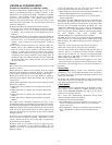
Indoor Thermostat Control Options
Model
Evolution
Control
Standard 2---stage
Thermostat
266A Yes Yes
Operating Ambient
The minimum outdoor operating ambient in cooling mode is 55_F
(12.78_C) without low ambient cooling enabled, and the
maximum outdoor operating ambient in cooling mode is 125_F
(51.67_C). At line voltage of 208v (or below) and an outdoor
ambient of 120_F (48.9_C) (and above), the compressor operates
in low stage. On Evolution communicating systems ONLY, low
ambient cooling operation is possible at ambient as low as 0_F
(--17.78_C).
The maximum outdoor operating ambient in heating mode is
66°F/18.89_C on all models.
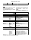
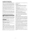
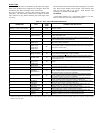
Model Plug
Each control board contains a model plug. The correct model plug
must be installed for or the system to operate properly. (See Table
22.)
Table 22—Model Plug Information
MODEL
NUMBER
MODEL PLUG
NUMBER
PIN RESISTANCE
(K --- ohms)
Pins 1 --- 4 Pins 2 --- 3
266ANA024 HK70EZ041 18 91
266ANA036 HK70EZ043 18 150
266ANA048 HK70EZ045 18 220
266ANA060 HK70EZ047 18 360
167ANA024 Hk70EZ040 18 75
167ANA036 Hk70EZ042 18 120
167ANA048 Hk70EZ044 18 180
167ANA060 Hk70EZ046 18 270
The model plug is used to identify the type and size of unit to the
control.
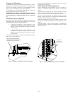
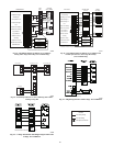
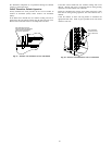
Airflow Selections for ECM Furnaces (non
communicating)
The ECM Furnaces provide blower operation to match the
capacities of the compressor during high and low stage cooling
operation. Tap selections on the furnace control board enable the
installing technician to select the proper airflows for each stage of
cooling. Below is a brief summary of the furnace airflow
configurations
1. The Y2 call for high stage cooling energizes the “Cool” tap
on the control board. The grey wire from cool tap is connec-
ted to tap 5 on the motor. Refer to the furnace Product Data
to find the corresponding airflow. If the airflow setting for
high cooling needs to be switched from tap 5 to a different
tap, jumper aconnection from the cool tap to the desired tap
so that the Y2 signal is communicated via the cool tap to the
desired speed tap.
2. The Y1 call for low stage cooling energizes the “Fan” tap
on the control board. The red wire from the fan tap is con-
nected to tap 1 on the motor. Refer to the furnace Product
Data to find the corresponding airflow. If the airflow setting
for low cooling needs to be switched from tap 1 to a differ-
ent tap, jumper a connection from the Fan tap to the desired
tap so that the Y1 signal is communicated via the Fan tap to
the desired speed tap. The Y1 setting will also govern the
continuous fan airflow for the furnace.
Refer to the furnace literature for further details.
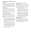
Airflow Selection for Variable Speed Furnaces
(non--communicating)
The variable speed furnaces provide blower operation to match the
capacities of the compressor during high and low stage cooling
operation. The furnace control board allows the installing
technician to select the proper airflows for each stage of cooling.
Below is a summary of required adjustments. See furnace
installation instructions for more details:
1. Turn SW1----5 ON for 400 CFM/ton airflow or OFF for 350
CFM/ton airflow. Factory default is OFF.
2. The A/C DIP switch setting determines airflow during high
stage cooling operation. Select the A/C DIP switch setting
corresponding to the available airflow shown in the furnace
Installation Instructions that most closely matches the re-
quired airflow shown in the air conditioning Product Data
for HIGH speed.
3. The CF DIP switch setting determines airflow during low
stage cooling operation. Select the CF DIP switch setting
corresponding to the available airflow shown in the furnace
installation instructions that most closely matches the re-
quired airflow shown in the air conditioning Product Data
for LOW speed. If a higher or lower continuous fan speed is
desired, the continuous fan speed can be changed using the
fan switch on the thermostat. Refer to the furnace Installa-
tion Instructions for details of how to use this feature.
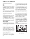
Airflow Selection for FV4C Fan Coils Using
Non--Communicating (Non--Evolution) Thermo-
stats
The FV4C provides high-- and low--stage blower operation to
match the capacities of compressor at high-- and low--stage. To
select recommended airflow, refer to FV4C Installation
Instructions. The FV4C utilizes an Easy Select control board that
allows the installing technician to select proper airflows. For
adjustments to control board, select appropriate HP SIZE and CFM
ADJUST setting. This fan coil has an adjustable blower off delay
factory set at 90 sec for high-- and low--stage blower operation.
When using a communicating (Evolution) control, dipswitch
adjustments are not necessary. Airflows are determined by
Evolution Control setup. The fan coil is the FE4A.
For other combinations of equipment consult Product Data Digest.
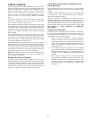
NOTE: Systems using only a non--communicating
(non--Evolution) thermostat, Bryant electronic thermostats are
equipped with a 15--minute staging timer. This timer prevents the
two--stage system from operating at high stage until unit has been
operating in low stage for 15 minutes, unless there is at least a ±5°F
(±2.8°C) difference between room temperature and thermostat set
point. To force high stage (after a minimum of 2 minutes in low
stage), adjust the set point at least ±5°F(±2.8°C) below room
ambient.