


29
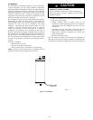
Thermostatic Expansion Valve (TXV)
All fan coils and furnace coils will have a factory installed
thermostatic expansion valve (TXV). The TXV will be a bi--flow,
hard--shutoff with an external equalizer and a balance port pin. A
hard shut--off TXV does not have a bleed port. Therefore,
minimal equalization takes place after shutdown. TXVs are
specifically designed to operate with Puronr or R--22 refrigerant,
use only factory authorized TXV’s. Do not interchange Puron
and R--22 TXVs.
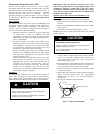
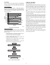
TXV
Operation
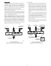
The TXV is a metering device that is used in air conditioning and
heat pump systems to adjust to changing load conditions by
maintaining a preset superheat temperature at the outlet of the
evaporator coil. The volume of refrigerant metered through the
valve seat is dependent upon the following:
1. Superheat temperature is sensed by cap tube sensing bulb
on suction tube at outlet of evaporator coil. This
temperature is converted into pressure by refrigerant in the
bulb pushing downward on the diaphragm which opens the
valve via the pushrods.
2. The suction pressure at the outlet of the evaporator coil is
transferred via the external equalizer tube to the underside
of the diaphragm. This is needed to account for the indoor
coil pressure drop. Residential coils typically have a high
pressure drop, which requires this valve feature.
3. The pin is spring loaded, which exerts pressure on the
underside of the diaphragm. Therefore, the bulb pressure
works against the spring pressure and evaporator suction
pressure to open the valve.
If the load increases, the temperature increases at the bulb,
which increases the pressure on the top side of the
diaphragm. This opens the valve and increases the flow of
refrigerant. The increased refrigerant flow causes the
leaving evaporator temperature to decrease. This lowers the
pressure on the diaphragm and closes the pin. The
refrigerant flow is effectively stabilized to the load demand
with negligible change in superheat.
Install
TXV
The thermostatic expansion valve is specifically designed to
operate with a refrigerant type. Do not use an R--22 TXV on a
Puron system, and do not use a Puron valve on an R--22 system.
Refer to Product Data Sheet for the appropriate TXV kit number.
CAUTION
!
UNIT OPERATION HAZARD
Failure to follow this caution may result in equipment
damage or improper operation.
Al indoor coil units must be installed with a hard shut
off PuronR TXV metering device.
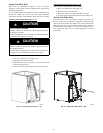
IMPORTANT: The TXV should be mounted as close to the
indoor coil as possible and in a vertical, upright position. Avoid
mounting the inlet tube vertically down. The valve is more
susceptible to malfunction due to debris if inlet tube is facing
down. A factory--approved filter drier must be installed in the
liquid line at the indoor unit.
Installing TXV in Place of Piston in a Rated Indoor
Coil
(pre--2006)
1. Pump system down to 2 psig and recover refrigerant.
2. Remove hex nut from piston body. Use backup wrench on
fan coils.
3. Remove and discard factory--installed piston. Be sure Teflon
seal is in place.
4. Reinstall hex nut. Finger tighten nut plus 1/2 turn.
NOTE: If the piston is not removed from the body, TXV will not
function properly.
CAUTION
!
EQUIPMENT DAMAGE HAZARD
Failure to follow this caution may result in equipment
damage or improper operation.
Use a brazing shield and wrap TXV with wet cloth or
use heat sink material
5. Install TXV on indoor coil liquid line. Sweat swivel adapter
to inlet of indoor coil and attach to TXV outlet. Use backup
wrench to avoid damage to tubing or valve. Sweat inlet of
TXV, marked “IN” to liquid line. Avoid excessive heat
which could damage valve.
6. Install vapor elbow with equalizer adapter to suction tube of
line set and suction connection to indoor coil. Adapter has a
1/4--in. male connector for attaching equalizer tube.
7. Connect equalizer tube of TXV to 1/4--in. equalizer fitting
on vapor line adapter.
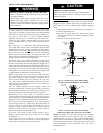
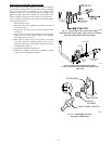
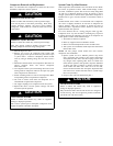
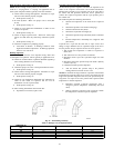
8. Attach TXV bulb to horizontal section of suction line using
clamps provided. Insulate bulb with field--supplied
insulation tape. See Fig. 25 for correct positioning of
sensing bulb.
9. Proceed with remainder of unit installation.
2O’CLOCK
10 O’CLOCK
SENSING BUL
B
STRAP
SUCTION TUBE
A08083
Fig. 25 – Position of Sensing Bulb