


26
Reversing
Valve
In heat pumps, changeover between heating and cooling modes is
accomplished with a valve that reverses flow of refrigerant in
system. This reversing valve device is easy to troubleshoot and
replace. The reversing valve solenoid can be checked with power
off with an ohmmeter. Check for continuity and shorting to
ground. With control circuit (24v) power on, check for correct
voltage at solenoid coil. Check for overheated solenoid.
With unit operating, other items can be checked, such as frost or
condensate water on refrigerant lines.
The sound made by a reversing valve as it begins or ends defrost is
a “whooshing” sound, as the valve reverses and pressures in system
equalize. An experienced service technician detects this sound and
uses it as a valuable troubleshooting tool.
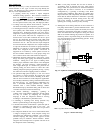
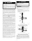
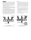
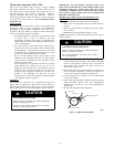
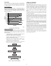
Using a remote measuring device, check inlet and outlet line
temperatures. DO NOT touch lines. If reversing valve is operating
normally, inlet and outlet temperatures on appropriate lines should
be close to each other. Any difference would be due to heat loss or
gain across valve body. Temperatures are best checked with a
remote reading electronic--type thermometer with multiple probes.
Route thermocouple leads to inside of coil area through service
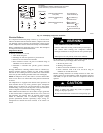
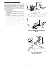
valve mounting plate area underneath coil. Fig. 20 and Fig. 21
show test points (TP) on reversing valve for recording
temperatures. Insulate points for more accurate reading.
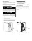
If valve is defective:
1. Shut off all power to unit and remove charge from system.
2. Remove solenoid coil from valve body. Remove valve by
cutting it from system with tubing cutter. Repair person
should cut in such a way that stubs can be easily re--brazed
back into system. Do not use hacksaw. This introduces
chips into system that cause failure. After defective valve is
removed, wrap it in wet rag and carefully unbraze stubs.
Save stubs for future use. Because defective valve is not
overheated, it can be analyzed for cause of failure when it is
returned.
3. Braze new valve onto used stubs. Keep stubs oriented
correctly. Scratch corresponding matching marks on old
valve and stubs and on new valve body to aid in lining up
new valve properly. When brazing stubs into valve, protect
valve body with wet rag to prevent overheating.
4. Use slip couplings to install new valve with stubs back into
system. Even if stubs are long, wrap valve with a wet rag to
prevent overheating.
5. After valve is brazed in, check for leaks. Evacuate and
charge system. Operate system in both modes several times
to be sure valve functions properly.
FROM INDOOR COIL
V
I
A
SERVICEVALVE ON
OUTDOOR COIL
TO
ACCUMULATOR
TO OUTDOOR
COIL
TP--4 TP--3
TP--2
TP--1
FROMCOMPRESSOR
DISCHARGE LINE
A88342
Fig. 20 – Reversing Valve
(Cooling Mode or Defrost Mode, Solenoid Energized)
TO INDOOR COIL
VIASERVICE VALVE
ON OUTDOOR COIL
TO
ACCUMULATOR
INSULATE
FOR
ACCURATE
READING
FROM
OUTDOOR
COIL
TP--4 TP--3
TP--2
TP--1
INSULATE FOR
ACCURATE
READING
FROM COMPRESSOR
DISCHARGE LINE
ELECTRONIC
THERMOMETER
A88341
Fig. 21 – Reversing Valve
(Heating Mode, Solenoid De--Energized)