


73
SYSTEM FUNCTIONS AND
SEQUENCE OF OPERATION
The 266A models utilize either an Evolution Communicating User
Interface or a 2-stage cooling indoor thermostat. With a call for
first stage cooling, the outdoor fan and low-stage compressor are
energized. If low-stage cannot satisfy cooling demand, high-stage
is energized by the second stage of indoor thermostat. After second
stage is satisfied, the unit returns to low-stage operation until first
stage is satisfied or until second stage is required again.
When both first stage and second stage cooling are satisfied, the
compressor will shut off. When a 2-stage unit is operating at
low-stage, system vapor (suction) pressure will be higher than a
standard single-stage system or high-stage operation.
When the outdoor ambient is more the 100_F (37.8_C), the
outdoor fan will continue to run for one minute after compressor
shuts off. This reduces pressure differential for easier starting in
the next cycle.
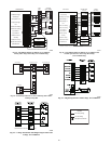
With non--communicating (non--Evolution) systems, with first
stage of cooling, Y1 and O are powered on; and with second stage
of cooling, Y1, Y2, and O are on. For these systems, with first
stage of heating Y1 is on and for second stage of heating, Y1 and
Y2 are on. When the reversing valve is energized, O is powered
on.
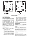
Communication and Status Function Lights
For Evolution Control only, Green communications (COMM)
Light
A green LED (COMM light) on the outdoor board indicates
successful communication with the other system products. The
green LED will remain OFF until communication is established.
Once a valid command is received, the green LED will turn ON
continuously. If no communication is received within 2 minutes,
the LED will be turned OFF until the next valid communication.
Amber Status
Light
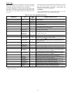
An amber colored STATUS light is used to display the operation
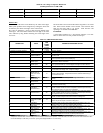
mode and fault codes as specified in the troubleshooting section.
See Table 23 for codes and definitions.
NOTE: Only one code will be displayed on the outdoor unit
control board (the most recent, with the highest priority).
Crankcase Heater Operation
The crankcase heater is energized during off cycle below 65°F
(18.33°C).
Outdoor Fan Motor Operation
The outdoor unit control energizes outdoor fan anytime
compressor is operating, except for defrost or low--ambient
cooling. The outdoor fan remains energized if a pressure switch or
compressor overload should open. Outdoor fan motor will
continue to operate for one minute after the compressor shuts off
when the outdoor ambient is greater than or equal to 100°F
(37.78°C). This reduces pressure differential for easier starting on
next cycle.
The outdoor fan motor is a PSC type. A fan relay on the control
board turns the fan off and on by opening and closing a high
voltage circuit to the motor. It does not change speeds between low
and high stage operation.
Time Delays
The unit time delays include:
S Five minute time delay to start cooling or heating operation
when there is a call from the thermostat or user interface. To
bypass this feature, momentarily short and release Forced
Defrost pins.
S Five minute compressor re--cycle delay on return from a
brown--out condition.
S Two minute time delay to return to standby operation from last
valid communication (with Evolution only).
S One minute time delay of outdoor fan at termination of cooling
mode when outdoor ambient is greater than or equal to 100_F
(37.78_C).
S Fifteen second delay at termination of defrost before the
auxiliary heat (W1) is de--energized.
S Twenty second delay at termination of defrost before the
outdoor fan is energized (unless fan delay defeated).
S Thirty second compressor delay when quiet shift enabled.
S There is no delay between staging from low to high and from
high to low capacity. The compressor will change from low to
high and from high to low capacity “on the fly” to meet the
demand.
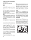
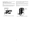
Compressor Operation
The basic scroll design has been modified with the addition of an
internal unloading mechanism that opens a by--pass port in thefirst
compression pocket, effectively reducing the displacement of the
scroll. The opening and closing of the by--pass port is controlled
by an internal electrically operated solenoid. The modulated scroll
uses a single step of unloading to go from full capacity to
approximately 67% capacity.
A single speed, high efficiency motor continues to run while the
scroll modulates between the two capacity steps. Modulation is
achieved by venting a portion of the gas in the first suction pocket
back to the low side of the compressor, thereby reducing the
effective displacement of the compressor.
Full capacity is achieved by blocking these vents, thus increasing
the displacement to 100%. A DC solenoid in the compressor
controlled by a rectified 24 volt AC signal in the external solenoid
plug moves the slider ring that covers and uncovers these vents.
The vent covers are arranged in such a manner that the compressor
operates at approximately 67% capacity when the solenoid is not
energized and 100% capacity when the solenoid is energized. The
loading and unloading of the two step scroll is done ”on the fly”
without shutting off the motor between steps.
NOTE: 67% compressor capacity translates to approximately 75%
cooling or heating capacity at the indoor coil.
The compressor will always start unloaded and stay unloaded for
five seconds even when the thermostat is calling for high stage
capacity.