


61
Muffler, Accumulator, Reversing Valve (RVS)
The Puronr two--stage air conditioners and heat pumps have a
compressor discharge line muffler, to dampen sound pressure
pulsations.
The Puronr two--stage heat pumps have a specifically designed
reversing valve, for Puronr application and an accumulator for
storing excess liquid refrigerant during the heating mode to prevent
damaging flood--back.
Thermistors
Outdoor Ambient Thermistor
The Puronr two--speed air conditioner and heat pump units have
an outdoor ambient air thermistor. The control board must know
the outdoor air temperature so it can activate various functions.
These functions include:
S Activating the compressor crankcase heater when ever
the outdoor unit is in the off cycle.
S The fan motor speed changes for both air conditioner
and heat pump on the ECM equipped units.
Outdoor Coil
Thermistor(OCT)
The coil or defrost thermistor is the same thermistor used to
monitor outdoor air temperature. The control board must know the
coil temperature so it can activate various functions. These
functions include:
S Frost sensing on heat pumps
S Coil--vs--Ambient temperature relationship
S Low ambient cooling operation
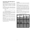
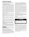
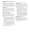
Thermistor
Curve
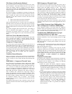
The resistance vs. temperature chart enables the service technicians
to check thermistor resistance, regardless of the temperature.
For example, at a 60_F temperature, thermistor resistance should
be around 16,000 Ohms. (See Fig. 43.)
We will talk about the thermistor in more detail when we review
the control board fault codes.
0
10
20
30
40
50
60
70
80
90
0
(-17.77)
20
(-6.67)
40
(4.44)
60
(15.56)
80
(26.67)
100
(37.78)
120
(48.89)
TEMPERATURE °F (°C)
RESISTANCE (KOHMS)
THERMISTOR CURVE
A08054
Fig. 43 – Resistance Values Versus Temperature
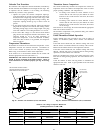
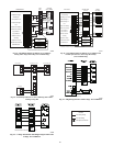
Control Box
Contactor And Capacitor
Removal of the information plate exposes the control components.
Both air conditioner and heat pump control boxes will appear to be
nearly identical. There are two contactors, two capacitors, a control
board and a compressor start assist. The contactors are identical to
those used in the standard single speed units. One controls low
capacity operation and the second controls high speed. The
capacitors also are similar to those used in standard single speed
units. You have a fan capacitor for the outdoor fan motor, and a run
capacitor for the compressor motor. The control board, start
capacitor, and start relay control the starting of the compressor.
Always replace these devices with the Factory Approved
Components.
Incoming
Power
Incoming power is attached to the two power wire stripped leads.
A ground lug is also provided. Outdoor unit should always be
grounded through the ground lug to the unit disconnect and from
the disconnect to the electrical fuse box. Failure to do so can cause
serious injury or death.
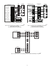
Start Circuit Sequence of Operation -- 187B &
286B
On a call for high-- or low--stage compressor operation, the start
relay is closed by the control board through the Vs, Vr, and L2
terminals. This puts the start capacitor in the circuit. Compressor
voltage is sensed on the VR and VS terminals throughout the
process. As the compressor comes up to speed, the control board
senses the change in voltage acrossVR and VS, and opens the start
relay at the appropriate voltage. The control is programmed with
the parameters for opening the start circuit. The voltage will be
different for high-- and low--stage, and for different unit sizes.
Since the same control board is used in all 2--stage units, the model
plug determines the start circuit voltage.
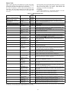
Troubleshooting 187B & 286B Start
Circuit:
If starting problems are encountered, the control board will flash
fault codes to help indicate where the problem was encountered.
See Table 21 for appropriate actions by active fault code.
S First check that the model plug is correct for the unit
model and size, and that it is installed properly
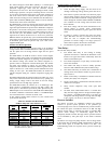
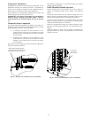
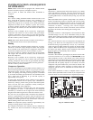
START CAPACITOR
MOUNTING HOLES
START RELAY
MOUNTING HOLE
TAB ON BOTTOM OF
START RELAY TO BE
PLACED IN THIS CORNER
A10157
Fig. 44 – Start Relay and Capacitor Mounting Locations
Evolution / Evolution in Cube Cabinet