


18
Deluxe Defrost Speedup (HK32EA003
CONT.)
To initiate a force defrost, speedup pins (J1) must be shorted with a
flat head screwdriver for 5 seconds and RELEASED. If the defrost
thermostat is open, a short defrost cycle will be observed (actual
length depends on Quiet Shift switch position). When Quiet Shift
is off, only a short 30 second defrost cycle is observed. With Quiet
Shift ON, the speed up sequence is one minute; 30 second
compressor off period followed by 30 seconds of defrost with
compressor operation. When returning to heating mode, the
compressor will turn off for an additional 30 seconds and the fan
for 40 seconds.
If the defrost thermostat is closed, a complete defrost cycle is
initiated. If the Quiet Shift switch is turned on, the compressor will
be turned off for two 30 second intervals as explained previously.
Troubleshooting (HK32EA003)
If outdoor unit will not run:
1. Does the Y input have 24 volts from thermostat? If not,
check thermostat or wire. If yes proceed to #2
2. The Y spade terminal should have 24 volts if Y input is
energized. This output goes through the pressure switches
and back to the T1 input to energize the time delay and
defrost timing circuit. If the contactor is not closed, the time
delay may still be active. Defeat time delay by shorting
speed up pins for 1 second. Be sure not to short more than 1
second.
3. Once time delay has elapsed voltage on T2 should energize
contactor. Check voltage on contactor coil. If no voltage is
present, check for opened pressure switch.
4. If voltage is present and contactor is open, contactor may be
defective. Replace contactor
5. If contactor is closed and unit will still not run, check
capacitor and compressor.
If unit will not go into defr
ost:
1. Perform speedup function as described above to test the
defrost function of the circuit board.
2. If the unit will go into defrost with the speed up, but will
not on its own, the defrost thermostat may not be
functioning properly. Perform the full defrost thermostat
and board troubleshooting the same as described for the
HK32EA001 control. Other than the Quiet shift (if
selected), and the speedup timing, the troubleshooting
process is identical.
3. If unit still will not run defrost, remove thermostat pigtail
harness from board and perform checks directly on input
pins with jumper wires. The pigtail may have a bad
connection or be mis--wired.
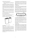
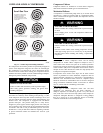
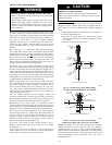
Fan Motor
The fan motor rotates the fan blade that draws air through the
outdoor coil to exchange heat between the refrigerant and the air.
Motors are totally enclosed to increase reliability. This eliminates
the need for a rain shield. For the correct position of fan blade
assembly, the fan hub should be flush with the motor shaft.
Replacement motors and blades may vary slightly.
ELECTRICAL SHOCK HAZARD
Failure to follow this warning could result in personal injury
or death.
Turn off all power before servicing or replacing fan motor. Be
sure unit main power switch is turned off.
!
WARNING
The bearings are permanently lubricated, therefore, no oil ports are
provided.
For suspected electrical failures, check for loose or faulty electrical
connections, or defective fan motor capacitor. Fan motor is
equipped with thermal overload device in motor windings which
may open under adverse operating conditions. Allow time for
motor to cool so device can reset. Further checking of motor can be
done with an ohmmeter. Set scale on R X 1 position, and check for
continuity between 3 leads. Replace motors that show an open
circuit in any of the windings. Place 1 lead of ohmmeter on each
motor lead. At same time, place other ohmmeter lead on motor case
(ground). Replace any motor that shows resistance to ground,
arcing, burning, or overheating.
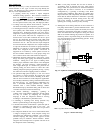
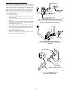
Compressor Plug
The compressor electrical plug provides a quick--tight connection
to compressor terminals. The plug completely covers the
compressor terminals and the mating female terminals are
completely encapsulated in plug. Therefore, terminals are isolated
from any moisture so corrosion and resultant pitted or discolored
terminals are reduced. The plug is oriented to relief slot in terminal
box so cover cannot be secured if wires are not positioned in slot,
assuring correct electrical connection at the compressor. The plug
can be removed by simultaneously pulling while “rocking“ plug.
However, these plugs can be used only on specific compressors.
The configuration around the fusite terminals is outlined on the
terminal covers. The slot through which wires of plug are routed is
oriented on the bottom and slightly to the left. The correct plug can
be connected easily to compressor terminals and plug wires can
easily be routed through slot terminal cover.
It is strongly recommended to replace the compressor plug should
a compressor fail due to a suspected electrical failure. At a
minimum, inspect plug for proper connection and good condition
on any compressor replacement.
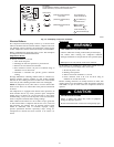
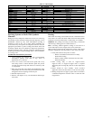
Low--Voltage Terminals
The low--voltage terminal designations, and their description and
function, are used on all split--system condensers.
W—Energizes first--stage supplemental heat through defrost relay
(wht).
R—Energizes 24--v power from transformer (red).
Y—Energizes contactor for first--stage cooling or first--stage
heating for heat pumps (yel).
O—Energizes reversing valve on heat pumps (orn).
C—Common side of transformer (blk).