


15
Defrost Thermostat
Defrost thermostat signals heat pump that conditions are right for
defrost or that conditions have changed to terminate defrost. It is a
thermally actuated switch clamped to outdoor coil to sense its
temperature. Normal temperature range is closed at 30_ ± 3_Fand
open at 65_ ± 5_F. Defrost thermostats are used in Legacy RNC
and Legacy Line models, a coil temperature thermistor is used in
Preferred and Evolution series units.
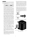
FEEDER TUBE
DEFROST
THERMOSTAT
STUB TUBE
A97517
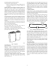
Fig. 8 – Defrost Thermostat Location
Check Defrost
Thermostat
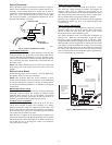
There is a liquid header with a brass distributor and feeder tube
going into outdoor coil. At the end of 1 of the feeder tubes, there is
a 3/8--in. OD stub tube approximately 3 in. long. (See Fig. 8.) The
defrost thermostat should be located on stub tube. Note that there is
only 1 stub tube used with a liquid header, and on most units it is
the bottom circuit.
NOTE: The defrost thermostat must be located on the liquid side
of the outdoor coil on the bottom circuit and as close to the coil as
possible.
Defrost Control Board
Troubleshooting defrost control involves a series of simple steps
that indicate whether or not board is defective.
NOTE: This procedure allows the service technician to check
control board and defrost thermostat for defects. First, troubleshoot
to make sure unit operates properly in heating and cooling modes.
This ensures operational problems are not attributed to the defrost
control board.
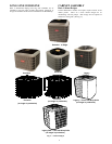
HK32EA001 Defrost
Control
The HK32EA001 defrost control is used in all Legacy RNC Line
heat pump models 213ANA and 213ANC. Its features include
selectable defrost intervals of 30, 60, 90 minutes, and standard
defrost speed up capability. This section describes the sequence of
operation and trouble shooting methods for this control.
Cooling Sequence of
Operation
On a call for cooling, thermostat makes R--O, R--Y, and R--G.
Circuit R--O energizes reversing valve switching it to cooling
position. Circuit R--Y sends low voltage through the safeties and
energizes the contactor, which starts the compressor and energizes
the T1 terminal on the circuit board. This will energize the OF2 fan
relay which starts the outdoor fan motor.
When the cycle is complete, R--Y is turned off and compressor and
outdoor fan should stop. With Bryant thermostats, the O terminal
remains energized in the cooling mode. If the mode is switched to
heat or Off, the valve is de--energized. There is no compressor
delay built into this control.
Heating Sequence of
Operation
On a call for heating, thermostat makes R--Y, and R--G. Circuit
R--Y sends low voltage through the safeties and energizes the
contactor, which starts the compressor and energizes the T1
terminal on the circuit board. The T1 terminal energizes the defrost
logic. This will energize the OF2 fan relay start the outdoor motor.
The T1 terminal must be energized for defrost to function.
When the cycle is complete, R--Y is turned off and the compressor
and outdoor fan should stop. There is no compressor delay built
into this control.
Defrost Sequence
(HK32EA001)
The defrost control is a time/temperature control that has field
selectable settings of 30, 60, and 90 minutes. These represent the
amount of time that must pass after closure of the defrost
thermostat before the defrost sequence begins.
The defrost thermostat senses coil temperature throughout the
heating cycle. When the coil temperature reaches the defrost
thermostat setting of approximately 32ºF, it will close, which
energizes the DFT terminal and begins the defrost timing sequence.
When the DTF has been energized for the selected time, the defrost
cycle begins, and the control shifts the reversing valve into cooling
position, and turns the outdoor fan off. This shifts hot gas flow into
the outdoor coil which melts the frost from the coil. The defrost
cycle is terminated when defrost thermostat opens at approximately
65_F, or automatically after 10 minutes.
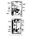
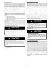
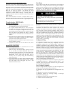
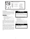
OUTDOOR FAN
RELAY
Y OUTPUT TO PRESSURE
SWITCHES AND CONTACTOR
THERMOSTAT INPUTS
T1 - ENABLES DEFROST
TIMER. MUST BE
ENERGIZED FOR
DEFROST TIMER
TO START
C - COMMON
O - REVERSING VALVE
SPEEDUP
HK32EA001
DEFROST THERMOSTAT
MUST BE CLOSED BEFORE
DEFROST TIMER BEGINS
A05332
Fig. 9 – HK32EA001 Defrost Control