


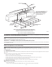
NOTE: Failure to use CPVC elbows may allow drain to kink and prevent draining.
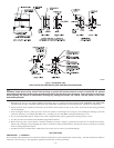
f. Connect larger diameter drain tube and clamp (factory-supplied in loose parts bag) to condensate trap and clamp securely.
g. Route tube to coupling and cut to appropriate length.
h. Attach tube to coupling and clamp securely.
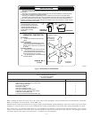
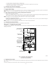
C. Condensate Trap Location (Alternate Upflow Orientation)
An alternate location for the condensate trap is the left-hand side of casing. (See Fig. 2 and 6.)
NOTE: If the alternate left-hand side of casing location is used, the factory-connected drain and relief port tubes must be disconnected and
modified for attachment. See Condensate Trap Tubing (Alternate Upflow Orientation) section for tubing attachment.
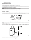
To relocate condensate trap to the left-hand side, perform the following:
1. Remove 3 tubes connected to condensate trap.
2. Remove trap from blower shelf by gently pushing tabs inward and rotating trap.
3. Install casing hole filler cap (factory-supplied in loose parts bag) into blower shelf hole where trap was removed.
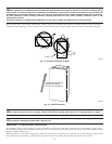
4. Install condensate trap into left-hand side casing hole by inserting tube connection stubs through casing hole and rotating until tabs snap
into locking position.
5. Fill unused condensate trap casing holes with plastic filler caps (factory-supplied in loose parts bag).
D. Condensate Trap Tubing (Alternate Upflow Orientation)
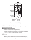
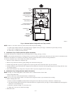
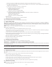
NOTE: See Fig. 6 or tube routing label on main furnace door to confirm location of these tubes.
1. Collector Box Drain Tube
Connect collector box drain tube (blue label) to condensate trap.
NOTE: On 17-1/2 in. wide furnaces ONLY, cut tube between corrugated sections to prevent kinks from occurring.
2. Inducer Housing Drain Tube
a. Remove and discard LOWER (molded) inducer housing drain tube which was previously connected to condensate trap.
b. Use inducer housing drain extension tube (violet label and factory-supplied in loose parts bag) to connect LOWER inducer housing drain
connection to the condensate trap.
c. Determine appropriate length, cut, and connect tube.
d. Clamp tube to prevent any condensate leakage.
3. Relief Port Tube
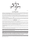
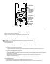
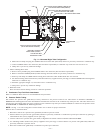
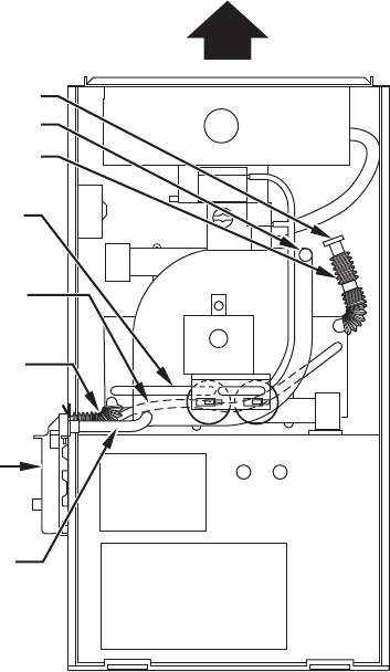
Fig. 6—Alternate Upflow Configuration and Trap Location
A94214
COLLECTOR BOX
TUBE (PINK)
CONDENSATE
TRAP
COLLECTOR BOX
TUBE (GREEN)
COLLECTOR BOX
DRAIN TUBE (GREEN)
INDUCER
HOUSING
DRAIN TUBE
(VIOLET)
CAP
COLLECTOR BOX
DRAIN TUBE (BLUE
& WHITE STRIPED)
PLUG
—8—