


Risers must be used to connect to furnace and to meter. Support all gas piping with appropriate straps, hangers, etc. Use a minimum of 1 hanger
every 6 ft. Joint compound (pipe dope) should be applied sparingly and only to male threads of joints. Pipe dope must be resistant to propane gas.
CAUTION: Connect gas pipe to furnace using a backup wrench to avoid damaging gas controls.
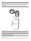
WARNING: Gas valve shutoff switch MUST be facing forward or tilted upward. Failure to follow this warning could
result in property damage or death.
WARNING: Never purge a gas line into a combustion chamber. Never use matches, candles, flame, or other sources
of ignition for purpose of checking leakage. Use a soap-and-water solution to check for leakage. Failure to follow this warning
could result in fire, explosion, personal injury, or death.
WARNING: Use proper length of pipe to avoid stress on gas control manifold. Failure to follow this warning could
result in a gas leak resulting in fire, explosion, personal injury, or death.
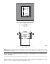
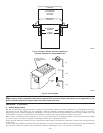
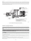
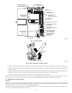
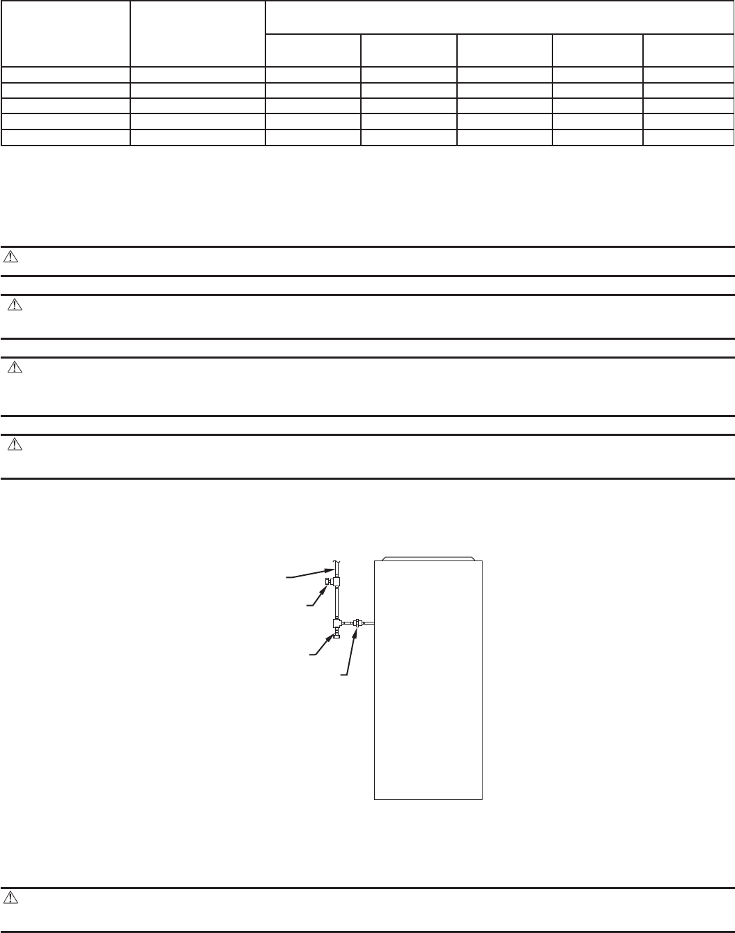
Install a sediment trap in riser leading to furnace. Trap can be installed by connecting a tee to riser leading to furnace so straight-through section
of tee is vertical. Then connect a capped nipple into lower end of tee. Capped nipple should extend below level of gas controls. Place a ground
joint union between gas control manifold and manual gas shutoff valve. (See Fig. 26.)
CAUTION: If a flexible connector is required or allowed by authority having jurisdiction, black iron pipe shall be
installed at gas valve and extend a minimum of 2 in. outside furnace casing.
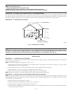
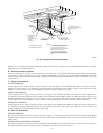
An accessible manual shutoff valve MUST be installed upstream of furnace gas controls and within 6 ft of furnace. A 1/8-in. NPT plugged tapping,
accessible for test gage connection, MUST be installed immediately upstream of gas supply connection to furnace and downstream of manual
shutoff valve.
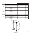
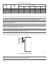
Table 3—Maximum Capacity of Pipe*
NOMINAL
IRON
PIPE
SIZE
(IN.)
INTERNAL
DIAMETER
(IN.)
LENGTH OF PIPE (FT)
10 20 30 40 50
1/2 0.622 175 120 97 82 73
3/4 0.824 360 250 200 170 151
1 1.049 680 465 375 320 285
1-1/4 1.380 1400 950 770 660 580
1-1/2 1.610 2100 1460 1180 990 900
* Cubic ft of gas per hr. for gas pressures of 0.5 psig (14–in. wc) or less and a pressure drop of 0.5–in wc (based on a 0.60 specific gravity gas).
Ref: NFGC.
Fig. 26—Typical Gas Pipe Arrangement
A93324
UNION
SEDIMENT
TRAP
MANUAL
SHUTOFF
VALVE
(REQUIRED)
GAS
SUPPLY
—24—