


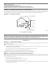
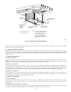
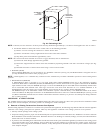
NOTE: The gas valve inlet press tap connection is suitable to use as test gage connection providing test pressure DOES NOT exceed maximum
0.5 psig (14-in. wc) stated on gas valve. (See Fig. 56.) Piping should be pressure tested in accordance with NFGC local and national plumbing
and gas codes before furnace is attached. In Canada, refer to current edition of NSCNGPIC. If pressure exceeds 0.5 psig (14-in. wc), gas supply
pipe must be disconnected from furnace and capped before pressure test. If test pressure is equal to or less than 0.5 psig (14-in. wc), turn off electric
shutoff switch located on gas valve before test. It is recommended that ground joint union be loosened before pressure testing. After all connections
have been made, purge lines and check for leakage.
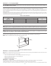
PROCEDURE 8—ELECTRICAL CONNECTIONS
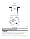
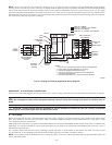
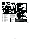
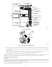
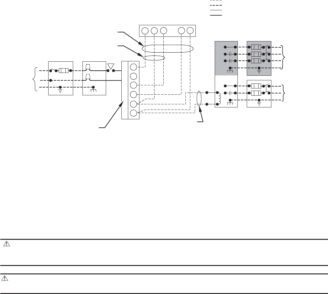
See Fig. 27 for field wiring diagram showing typical field 115-v and 24-v wiring. Check all factory and field electrical connections for tightness.
WARNING:
Blower access panel door switch opens 115-v power to control center. No component operation can
occur. Do not bypass or close switch with panel removed. Failure to follow this warning could result in personal injury or
death.
CAUTION: Furnace control must be grounded for proper operation or control will lock out. Control is grounded
through green wire routed to gas valve and burner box screw.
A. 115-V Wiring
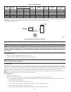
Before proceeding with electrical connections, make certain that voltage, frequency, and phase correspond to that specified on the furnace rating
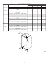
plate. Also, check to be sure that service provided by utility is sufficient to handle load imposed by this equipment. Refer to rating plate or Table
4 for equipment electrical specifications.
Make all electrical connections in accordance with National Electrical Code (NEC) ANSI/NFPA 70-2002 and any local codes or ordinances that
might apply. For Canadian installations, all electrical connections must be made in accordance with Canadian Electrical Code CSA C22.1 or
authorities having jurisdiction.
Use a separate, fused branch electrical circuit containing a properly sized fuse or circuit breaker for this furnace. See Table 4 for wire size and
fuse specifications. A disconnecting means must be located within sight from and readily accessible to furnace.
NOTE: Proper polarity must be maintained for 115-v wiring. If polarity is incorrect, control LED status indicator light will flash rapidly and
furnace will NOT operate.
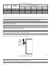
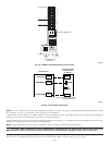
Fig. 27—Heating and Cooling Application Wiring Diagram
A98325
115-V
FIELD-SUPPLIED
DISCONNECT
SWITCH
115-V
SINGLE
PHASE
AUXILIARY
J-BOX
FURNACE
CONTROL
CENTER
TWO WIRE
24-V
TERMINAL
BLOCK
THREE-WIRE
HEATING
ONLY
FIVE
WIRE
NOTE 5
NOTE 1
NOTE
3
THERMOSTAT
TERMINALS
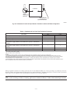
FIELD-SUPPLIED
DISCONNECT
CONDENSING
UNIT
R
W2
WCR GY
GND
GND
GND
GND
FIELD 24-V WIRING
FIELD 115-, 208/230-, 460-V WIRING
FACTORY 24-V WIRING
FACTORY 115-, 208/230-, 460-V WIRING
208/230- OR
460-V
THREE PHASE
208/230-V
SINGLE
PHASE
W/W1
Y/Y2
G
C
NOTES:
1.
2.
3.
4.
5.
Connect Y or Y/Y2 terminal as shown for proper cooling operation.
Proper polarity must be maintained for 115-v wiring.
Use W2 with 2-stage thermostat when zoning.
If any of the original wire, as supplied, must be replaced, use
same type or equivalent wire.
Some thermostats require a "C" terminal connection as shown.
—25—