


PROCEDURE 2—UPFLOW APPLICATIONS
In an upflow application, the blower is located below the burner section, and conditioned air is discharged upwards.
A. Condensate Trap Location (Factory-Shipped Orientation)
The condensate trap is factory installed in the blower shelf and factory connected for UPFLOW applications. A factory-supplied tube is used to
extend the condensate trap drain connection to the desired furnace side for field drain attachment. See Condensate Trap Tubing (Factory-Shipped
Orientation) section for drain tube extension details.
B. Condensate Trap Tubing (Factory-Shipped Orientation)
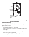
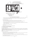
NOTE: See Fig. 5 or tube routing label on main furnace door to confirm location of these tubes.
1. Collector Box Drain, Inducer Housing Drain, Relief Port, and Pressure Switch Tubes.
These tubes should be factory attached to condensate trap and pressure switch ready for use in upflow applications. These tubes can be
identified by their connection location and also by a color label on each tube. These tubes are identified as follows: collector box drain tube
(blue label), inducer housing drain tube (violet label or molded), relief port tube (green label), and pressure switch tube (pink label).
2. Condensate Trap Drain Tube.
The condensate trap drain connection must be extended for field attachment by doing the following:
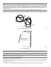
a. Determine location of field drain connection. (See Fig. 2 or 5.)
NOTE: If internal filter or side Filter/Media Cabinet is used, drain tube should be located to opposite side of casing of return duct attachment
to assist in filter removal.
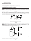
b. Remove and discard casing drain hole plug button from desired side.
c. Install drain tube coupling grommet (factory-supplied in loose parts bag) in selected casing hole.
d. Slide drain tube coupling (factory-supplied in loose parts bag) through grommet ensuring long end of coupling faces blower.
e. Cement 2 factory-supplied 1/2-in. street CPVC elbows to the rigid drain tube connection on the condensate trap. (See Fig. 5.) These
elbows must be cemented together and cemented to condensate trap drain connection.
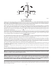
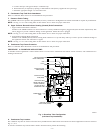
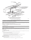
Fig. 5—Factory-Shipped Upflow Tube Configuration
(Shown with Blower Access Panel Removed)
A94213
COLLECTOR BOX
TUBE (PINK)
COLLECTOR BOX
TUBE (GREEN)
INDUCER HOUSING
(MOLDED) DRAIN
TUBE (BEHIND
COLLECTOR BOX
DRAIN TUBE)
COLLECTOR BOX
DRAIN TUBE (BLUE)
FIELD-INSTALLED
FACTORY-SUPPLIED
DRAIN TUBE
COUPLING (LEFT
DRAIN OPTION)
FIELD-INSTALLED
FACTORY-SUPPLIED
DRAIN TUBE
FIELD-INSTALLED
FACTORY-SUPPLIED
DRAIN TUBE
COUPLING (RIGHT
DRAIN OPTION)
CAP
COLLECTOR BOX
DRAIN TUBE (BLUE
& WHITE STRIPED)
PLUG
FIELD-INSTALLED
FACTORY-SUPPLIED
1
Ú2 -IN. CPVC STREET
ELBOWS (2) FOR
LEFT DRAIN OPTION
CONDENSATE
TRAP
—7—