


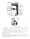
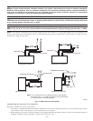
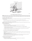
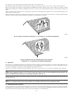
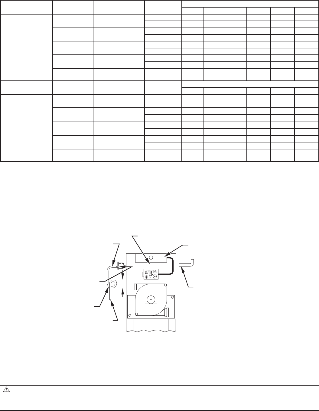
If use of this drain connection is desired, drill out fitting’s tap plug with a 3/16-in. drill and connect a field-supplied 3/8-in. tube. This tube should
be routed to open condensate drain for furnace and A/C (if used), and should be trapped. (See Fig. 38.)
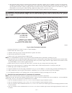
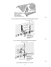
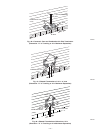
2. Attach vent pipe to furnace as follows:
a. Determine location of vent pipe connection to inducer housing as shown in Fig. 36 for application.
b. Reposition elastomeric (rubber) inducer housing outlet cap and clamp to appropriate unused inducer housing connection. Tighten clamp.
WARNING: Inducer housing outlet cap must be installed and fully seated against inducer housing. Clamp must be
tightened to prevent any condensate leakage. Failure to follow this warning could result in electrical shock, fire, personal
injury, or death.
c. Install pipe support (factory-supplied in loose parts bag) into selected furnace casing vent pipe hole. Pipe support should be positioned
at bottom of casing hole.
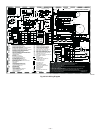
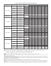
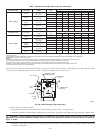
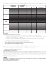
Table 7—Maximum Allowable Pipe Length (ft) (Continued)
ALTITUDE (FT) UNIT SIZE
TERMINATION
TYPE
PIPE DIA
(IN.)*
NUMBER OF 90° ELBOWS
123 4 5 6
8001 to 9000‡
042040
2 Pipe or 2-in
Concentric
1-1/2 30 25 20 15 10 5
2 626058 56 55 53
042060
2 Pipe or 2-in
Concentric
1-1/2 30 25 20 15 10 5
2 626058 56 55 53
042080
060080
2 Pipe or 2-in
Concentric
1-1/2 17 12 7 NA NA NA
2 626058 56 51 46
060100
2 Pipe or 2-in
Concentric
2 272217 12 7 NA
2-1/2 62 60 58 56 55 53
060120
2 Pipe or 3-in.
Concentric
3† 43 41 39 37 35 34
ALTITUDE (FT) UNIT SIZE
TERMINATION
TYPE
PIPE DIA
(IN.)*
NUMBER OF 90° ELBOWS
123 4 5 6
9001 to 10,000‡
042040
2 Pipe or 2-in
Concentric
1-1/2 27 22 17 12 7 NA
2 575553 51 49 47
042060
2 Pipe or 2-in
Concentric
1-1/2 27 22 17 12 7 NA
2 575553 51 49 47
042080
060080
2 Pipe or 2-in
Concentric
1-1/2 15 10 5 NA NA NA
2 575553 51 46 41
060100
2 Pipe or 2-in
Concentric
2 241914 9 NANA
2-1/2 57 55 53 51 49 47
060120
2 Pipe or 3-in.
Concentric
3 393735 33 31 29
Disk usage-Unless otherwise specified, use perforated disk assembly (factory-supplied in loose parts bag)
†Wide radius elbow.
‡Vent sizing for Canadian installations over 4500 ft (1370 m) above sea level are subject to acceptance by the local authorities having jurisdiction.
NA-Not Allowed; pressure switch will not make.
NOTES:
1. Do not use pipe size greater than those specified in table or incomplete combustion, flame disturbance, or flame sense lockout may occur.
2. Size both the combustion-air and vent pipe independently, then use the larger of these two diameters for both pipes.
3. Assume two 45° elbows equal one 90° elbow. Long radius elbows are desirable and may be required in some cases.
4. Elbows and pipe sections within the furnace casing and at the vent termination should not be included in vent length or elbow count.
5. The minimum pipe length is 5 ft for all applications.
Fig. 38—Intake Housing Plug Fitting Drain
A93035
COMBUSTION
AIR PIPE
BURNER
BOX
COMBUSTION AIR
INTAKE HOUSING
3/8" ID TUBE
TRAP
TO OPEN
DRAIN
3/16"
DRILL
4″
(102mm)
MIN
—36—