


NOTE: If desired, cut butt connectors off factory leads and strip insulation approximately 1/4 in and use field-supplied wire nuts to connect.
b. An alternate method to attach EAC lead to control center is the following procedure:
(1.) Remove 2 screws securing the control box to furnace blower shelf.
(2.) Remove and discard 2 factory-supplied leads from control center EAC terminals.
(3.) Strip EAC power leads insulation approximately 1/8 in.
NOTE: The control center EAC terminals are sized for 12 gage maximum, solid or stranded wire.
(4.) Route EAC leads through right-hand wire grommet.
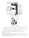
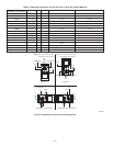
(5.) Insert EAC stripped leads into control center EAC terminals by depressing terminal’s arm with a screwdriver or finger. (See Fig.
32.)
(6.) Reinstall control box to furnace blower shelf using 2 screws removed earlier.
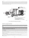
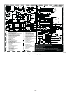
2. Humidifier (HUM)
Screw terminals (HUM and C
OM) are provided for 24-v humidifier connection. (See Fig. 30.) The HUM terminal is energized with 24-v
(0.5-amp maximum) after inducer motor prepurge period.
NOTE: A field-supplied, 115–v controlled relay connected to EAC terminals may be added if humidifier operation is desired during blower
operation.
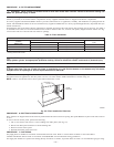
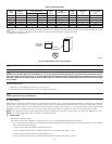
3. Dehumidification (DEHUM)
A dehumidification input is provided via a 1/4-in. male quick-connect labeled DEHUM located next to the transformer secondary
connections. When there is a dehumidify demand, the DEHUM input is activated, which means 24 vac signal is removed from the DEHUM
input terminal. In other words, the DEHUM input logic is reversed. the DEHUM input is turned ON when no dehumidify demand exists
and is turned OFF when demand exists. This logic reversal has come about from historical use of a standard humidistat to do
dehumidification since the contacts open on high humidity, thus removing the 24-v signal to initiate dehumidification.
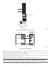
The DEHUM output on the thermidistat control or the humidistat output is connected directly to the DEHUM terminal on the furnace
control. In addition, the DE jumper located next to the DEHUM terminal must be removed to enable the DEHUM input. (See Fig. 33 and
34.) When a dehumidify demand exists, the furnace control reduces the blower airflow by 21 percent to 315 CFM per ton during continuous
fan or cooling operation.
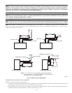
PROCEDURE 9—DIRECT VENTING
The 355MAV furnaces require a dedicated (one 355MAV furnace only) direct-vent system. In a direct-vent system, all air for combustion is taken
directly from outside atmosphere, and all flue products are discharged to outside atmosphere.
A. Removal of Existing Furnaces from Common Vent Systems
If furnace being replaced was connected to a common vent system with other appliances, the following steps shall be followed with each appliance
connected to the venting system placed in operation, while any other appliances connected to the venting system are not in operation:
1. Seal any unused openings in the venting system.
2. Inspect the venting system for proper size and horizontal pitch as required in the National Fuel Gas Code, ANSI Z223.1 or 24 the CAN/CGA
B149 Installation Codes and these instructions. Determine that there is no blockage or restriction, leakage, corrosion, and other deficiencies
which could cause an unsafe condition.
3. If practical, close all building doors and windows and all doors between the space in which the appliance(s) connected to the venting system
are located and other spaces of the building. Turn on clothes dryers and any appliance not connected to the venting system. Turn on any
exhaust fans, such as range hoods and bathroom exhausts, so they shall operate at maximum speed. Do not operate a summer exhaust fan.
Close fireplace dampers.
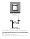
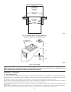
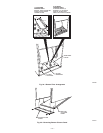
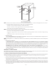
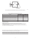
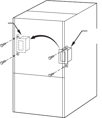
Fig. 29—Relocating J-Box
A00212
FACTORY
INSTALLED
LOCATION
ALTERNATE
FIELD
LOCATION
—27—