


Before installing the furnace in Canada, refer to the current edition of the NSCNGPIC. Contact Standard Sales CSA International, 178 Rexdale
Boulevard, Etobicoke, (Toronto) Ontario, Canada M9W 1R3.
Installation must comply with regulations of serving gas supplier and local building, heating, plumbing or other codes in effect in the area in which
installation is made. In absence of local codes, installation must comply with the NFGC in the United States and the NSCNGPIC in Canada.
These instructions cover minimum requirements for a safe installation and conform to existing national standards and safety codes. In some
instances, these instructions exceed certain local codes and ordinances, especially those that may not have kept pace with changing residential
construction practices. We require these instructions as a minimum for a safe installation.
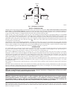
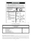
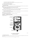
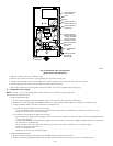
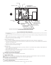
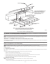
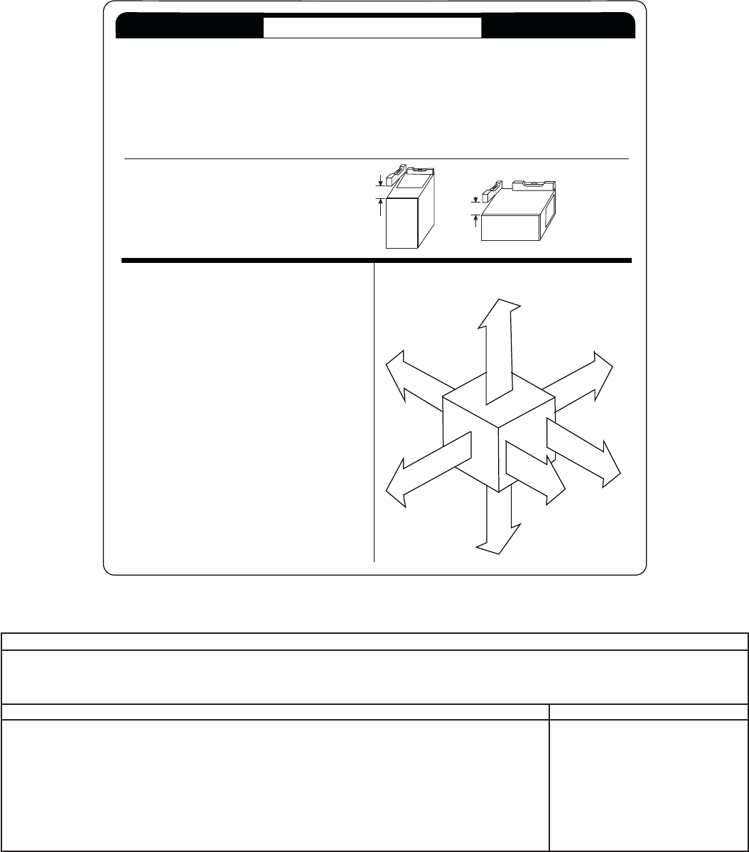
Fig. 3—Clearances to Combustibles
A99103
FRONT
FRONT
This forced air furnace is equipped for use with natural gas at altitudes 0 - 10,000 ft (0 - 3,050m).
An accessory kit, supplied by the manufacturer, shall be used to convert to propane gas use or may be required for some natural
gas applications.
This furnace is for indoor installation in a building constructed on site. This furnace may be installed in a manufactured (mobile)
home when stated on rating plate and using factory authorized kit.
This furnace may be installed on combustible flooring in alcove or closet at minimum clearance from combustible material.
This appliance requires a special venting system. Refer to the installation instructions for parts list and method of installation. This
furnace is for use with schedule-40 PVC, PVC-DWV, or ABS-DWV pipe, and must not be vented in common with other gas-fired
appliances. Construction through which vent/air intake pipes may be installed is maximum 24 inches (600 mm), minimum 3/4 inches
(19 mm) thickness (including roofing materials).
Clearance in inches.
Vent clearance to
combustibles 0".
This furnace is approved for UPFLOW, DOWNFLOW and
HORIZONTAL installations.
*
BOTTOM
0"
Ø
3"
0"
§
0"
TOP/PLENUM
1"
0"
§
30
MIN
ALL POSITIONS:
S
I
D
E
F
R
O
N
T
B
C
K
A
S
E
R
V
I
E
C
F
R
O
N
T
S
I
D
E
U
F
R
N
A
C
E
Clearance arrows
do not change with
furnace orientation.
†
HORIZONTAL
UPFLOW OR
DOWNFLOW
1/2" MAX
1/2" MAX
TO
LEVEL (0")
LEVEL (0")
TO
325400-201 REV. A
MINIMUM INCHES CLEARANCE TO
COMBUSTIBLE CONSTRUCTION
†
HORIZONTAL POSITIONS:
DOWNFLOW POSITIONS:
§
Ø
*
Mimimum front clearance for service 30 inches
(762mm).
For installation on combustible floors only when
installed on special base No. KGASB0201ALL, Coil
Assembly, Part No. CD5 or CK5, or Coil Casing, Part
No. KCAKC.
Clearance shown is for air inlet and air outlet end.
Line contact is permissible only between lines
formed by intersections of top and two sides of furnace
jacket, and building joists, studs, or framing.
120 size Furnace require 1 inch bottom clearance to
combustible materials.
Furnace must be installed level, or
pitched forward within 1/2 inch of level
for proper drainage. Failure will result in
equipment or property damage. See
Installation Manual for IMPORTANT unit
support details on horizontal
applications.
INSTALLATION
(LIT. TOP)
INSTALLER PACKET INCLUDES:
Installation, Startup, and Operating Instructions
Service and Maintenance Instructions
User’s Information Manual
Warranty Certificate
Loose Parts Bag includes: Quantity
Pressure tube extension
Collector Box or condensate trap extension tube
Inducer housing drain tube
1/2-in CPVC street elbow
Drain tube coupling
Drain tube coupling grommet
Vent and combustion-air pipe support
Combustion-air pipe perforated disk assembly
Condensate trap hole filler plug
Vent and combustion-air intake hole filler plug
1
1
1
2
1
1
2
1
3
2
—5—