


1. Leave 115-v power to furnace turned on.
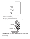
2. Remove main furnace door.
3. Remove blower access panel.
4. Move setup switch SW-6 to ON position.
5. Manually close blower access panel door switch. Use a piece of tape to hold switch closed.
WARNING: Blower access panel door switch opens 115-v power to control center. No component operation can
occur. Caution must be taken when manually closing this switch for service purposes. Failure to follow this warning could
result in personal injury or death.
When items 1-5 have been completed, the following will occur:
1. The control center goes through a brief self-test. This self-test takes approximately 2 sec to complete. After door switch is closed, red
(microprocessor) LED briefly comes on. Then green LED comes on for 1 sec, followed by 1 sec where both green and yellow LEDs are
on. During this time, the microprocessor is checking itself.
2. Inducer motor operates for 20 sec at low speed, operates for 20 sec at high speed, then turns off. Hot surface ignitor is energized for 15
sec, then de-energized.
3. Main blower motor operates for 20 sec at low speed, operates for 20 sec at high speed, then turns off.
4. After component operation test is completed, 1 or more fault codes (11, 22, 41, or 42) will flash. See service label on back of main furnace
door for explanation of fault codes.
NOTE: To repeat component test, turn setup switch SW-6 to OFF and then back to ON.
After component test, perform the following:
1. Release blower panel access door switch and turn setup switch SW-6 to OFF position.
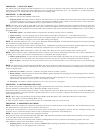
2. If applicable, replace blower access panel and check LED status by removing plug in blower access panel.
3. Reinstall main furnace door if all LEDs are off, indicating furnace is ready to operate when a signal from thermostat is received.
PROCEDURE 9—BYPASS HUMIDIFIER MODE
When setup switch SW-3 BPH is in ON position, RPM calculated for low heat is multiplied by 1.15 for all furnace model sizes. This compensates
for increased return-air temperature caused by bypassed air supply.
PROCEDURE 10—DEHUMIDIFICATION MODE
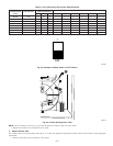
A dehumidification input is provided via a 1/4 in. male quick-connect terminal labeled DEHUM located next to the transformer secondary
connections. When there is a dehumidify demand, the DEHUM input is activated, which means 24 vac signal is removed from the DEHUM input
terminal. In other words, the DEHUM input logic is reversed. the DEHUM input is turned ON when no dehumidify demand exists and is turned
OFF when demand exists. This logic reversal has come about from historical use of a standard humidistat to do dehumidification since the contacts
open on high humidity, thus removing the 24-v signal to initiate dehumidification.
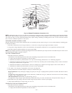
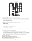
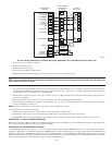
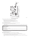
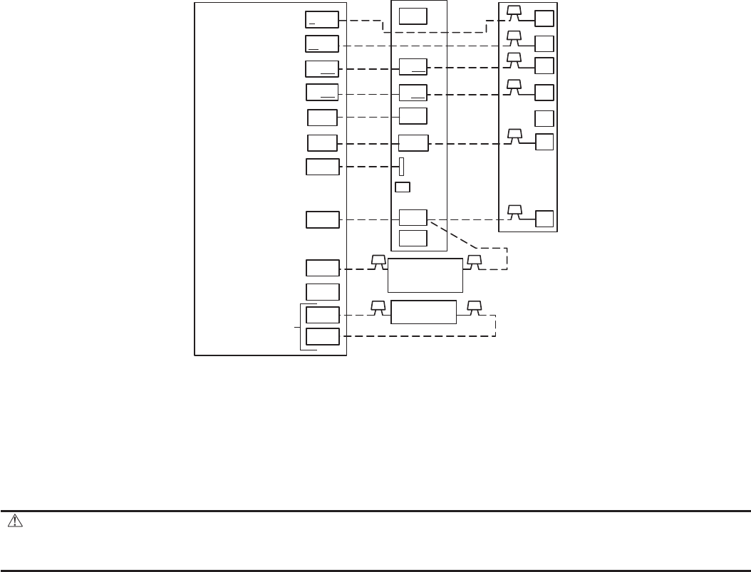
Fig. 52—Wiring Schematic for 2-Speed Heat Pump Application with Thermidistat Control (Dual Fuel)
A01474
HUMIDIFIER
SOLENOID VALVE
(24 VAC)
O/W2
Y1/W2
W/W1
G
R
W2
THERMIDISTAT™
CONTROL
VARIABLE-SPEED
CONDENSING
FURNACE
2-SPEED
HEAT PUMP
W/W1
G
C
R
C
DHUM
HUM
B
S1
S2
Y/Y2
R
DEHUM
DE
COM
HUM
RVS COOLING
FAN
24 VAC HOT
24 VAC COMM
DEHUMIDIFY
HUMIDIFY
N/A
OUTDOOR
SENSOR
CONNECTION
Y/Y2
OUTDOOR
SENSOR
Y2
W3
Y1
W2
O
HEAT STAGE 3
(FURNACE)
HEAT/COOL
STAGE 1
(COMPRESSOR LO)
HEAT/COOL
STAGE 2
(COMPRESSOR HI)
—47—