


2. Blower on—The blower motor is turned on IMMEDIATELY and slowly increases to maximum speed as soon as a call for heat is received.
No blower calibration occurs.
3. Electronic Air Cleaner—The EAC-1 terminal does not operate in emergency heat mode.
4. Humidifier—The HUM terminal is energized IMMEDIATELY.
5. Ignitor warm up—The HSI is energized for a 17 sec warm-up period after prepurge period is completed.
6. Ignition sequence—After HSI warm-up period has completed, the gas valve is energized, permitting gas flow to burners where it is ignited.
After 5 sec, the HSI is de-energized, and a 2-sec flame-sensing period begins.
NOTE: Emergency heat mode only operates in high heat.
7. Flame sensing—When burner flame is sensed, control center holds gas valve open. If burner flame is not sensed, control center de-energizes
gas valve and ignition sequence is repeated.
NOTE: Ignition sequence repeats 3 additional times before lockout occurs. Lockout automatically resets after 3 hr, or can be manually reset by
turning 115-v or 24-v power off (not at thermostat) for 3 sec minimum, then turning on again. Fault codes will not flash in emergency heat mode.
8. Blower off delay—When thermostat is satisfied, the R-W/W1 signal is terminated, de-energizing gas valve (stopping gas flow to burners),
and HUM terminal is de-energized. The blower stops immediately.
9. Post purge—Post purge does NOT occur. The inducer stops immediately.
PROCEDURE 5—COOLING MODE
A. Single-Speed Applications
When thermostat calls for cooling, the R-G and R-Y/Y2 circuits close.
1. Cooling unit—The cooling unit starts when thermostat R-Y signal is received.
2. Blower on—The control center starts blower immediately when it receives an R-Y/Y2 and R-G signal. The blower starts at approximately
400-500 RPM. After 20 sec, the blower is turned off for 1/10 of a sec where a coast down calibration is done to evaluate resistance of the
conditioned air duct system. The microprocessor then determines blower RPM required to provide selected cooling airflow.
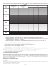
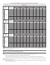
NOTE: In cooling mode, the microprocessor adjusts blower RPM to operate at 400 CFM per ton as selected on A/C setup switches. Airflow will
be reduced to 315 CFM per ton when a dehumidification demand exists. See Air Conditioning Setup Switches section. There is also a chart on
wiring diagram. (See Fig. 30.)
NOTE: If Y/Y2 thermostat lead is not connected to furnace control center, blower motor operates in continuous fan speed and indoor coil
freeze-up may occur.
3. Electronic Air Cleaner—The EAC-1 terminal is energized whenever blower operates.
4. Cooling unit—The cooling unit stops when thermostat R-Y signal is terminated.
5. Blower off delay—When thermostat is satisfied, the R-Y/Y2 and R-G signals are terminated, and blower remains operating for 90 sec. The
blower airflow will drop by 21 percent during the off-delay period when the DE jumper is connected. The DE jumper is only removed to
enable the DEHUM input for use with a thermidistat or humidistat for dehumidification purposes.
B. Two-Speed Applications
For details on 2-speed cooling applications, refer to Fig. 51.
PROCEDURE 6—HEAT PUMP MODE
A. Single-Speed Applications
When furnace is operating in heat pump heating mode, R-Y/Y2 and R-G circuits are closed energizing heat pump, and blower operates at cooling
speed. When heat pump defrost is required, R-W/W1 circuits close starting gas heat cycle, and blower adjusts to low-heat speed.
1. Prepurge period—The inducer motor is turned on and slowly comes up to speed. When low-pressure switch closes, inducer motor RPM
is noted by microprocessor, and a 25 sec prepurge period begins. The RPM is used to evaluate vent system resistance. This evaluation is
then used to determine required RPM necessary to operate inducer in low-heat mode.
NOTE: The heat cycle can start in either high or low heat. If a high-heat cycle is initiated, inducer continues increasing its speed after low-pressure
switch closes. When high-pressure switch closes, inducer motor RPM is noted by microprocessor before the 25 sec prepurge period begins. The
RPM is used to evaluate vent system resistance. This evaluation is used to determine required RPM necessary to operate inducer in high-heat mode.
2. Humidifier—The HUM terminal is energized after inducer prepurge period is completed.
3. Ignitor warm up—After prepurge period, HSI is energized for 17 sec.
4. Ignition sequence—After HSI warm-up period is completed, the gas valve is energized, permitting gas flow to the burners where it is
ignited. After 5 sec, the HSI is de-energized, and a 2-sec flame-sensing period begins.
5. Flame sensing—When burner flame is sensed, control center holds gas valve open.
If burner flame is not sensed, control center de-energizes gas valve, and ignition sequence is repeated.
6. Blower off period—Ten sec after gas valve is energized, the blower stops for 25 sec to allow heat exchangers to warm up.
7. Blower on delay—After blower off period, blower starts.
NOTE: The blower starts at approximately 400-500 RPM. After 20 sec, the motor is turned off for 1/10 of a sec where a coast down calibration
is done to evaluate resistance of the conditioned air duct system. The microprocessor then determines blower RPM required to provide proper
airflow for heating mode.
—45—