


Maintain a 1-in. clearance from combustible materials to supply air ductwork for a distance of 36 in. horizontally from the furnace. See NFPA
90B or local code for further requirements.
B. Ductwork Acoustical Treatment
Metal duct systems that do not have a 90 degree elbow and 10 ft of main duct to the first branch take-off may require internal acoustical lining.
As an alternative, fibrous ductwork may be used if constructed and installed in accordance with the latest edition of SMACNA construction
standard on fibrous glass ducts. Both acoustical lining and fibrous ductwork shall comply with NFPA 90B as tested by UL Standard 181 for Class
1 Rigid air ducts.
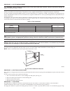
C. Supply Air Connections
UPFLOW FURNACES
Connect supply-air duct to 3/4-in. flange on furnace supply-air outlet. The supply-air duct attachment must ONLY be connected to furnace
supply-/outlet-air duct flanges or air conditioning coil casing (when used). DO NOT cut main furnace casing to attach supply side air duct,
humidifier, or other accessories. All accessories MUST be connected external to furnace main casing.
DOWNFLOW FURNACES
Connect supply-air duct to supply-air opening on furnace. The supply-air duct attachment must ONLY be connected to furnace supply/outlet or
air conditioning coil casing (when used), when installed on non-combustible material. When installed on combustible material, supply-air duct
attachment must ONLY be connected to an accessory subbase or factory approved air conditioning coil casing. DO NOT cut main furnace casing
to attach supply side air duct, humidifier, or other accessories. All accessories MUST be connected external to furnace main casing.
HORIZONTAL FURNACES
Connect supply-air duct to supply air opening on furnace. The supply-air duct attachment must ONLY be connected to furnace supply/outlet or
air conditioning coil casing (when used). DO NOT cut main furnace casing to attach supply side air duct, humidifier, or other accessories. All
accessories MUST be connected external to furnace main casing.
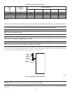
D. Return Air Connections
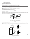
UPFLOW FURNACES
The return-air duct must be connected to bottom, sides (left or right), or a combination of bottom and side(s) of main furnace casing. Bypass
humidifier may be attached into unused side return air portion of the furnace casing. DO NOT connect any portion of return-air duct to back of
furnace casing.
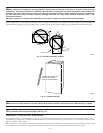
DOWNFLOW AND HORIZONTAL FURNACES
The return-air duct must be connected to return-air opening provided. DO NOT cut into casing sides or back to attach any portion of return-air
duct. Bypass humidifier connections should be made at ductwork or coil casing sides exterior to furnace.
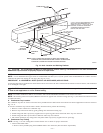
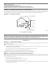
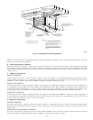
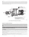
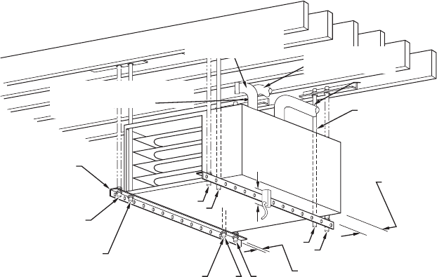
Fig. 22—Crawlspace Horizontal Application
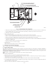
A93304
NOTES:
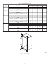
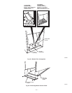
ANGLE
IRON OR
EQUIVALENT
(B)
(A) ROD LOCATION
USING DIMPLE
LOCATORS
(SEE DIMENSIONAL
DWG FOR
LOCATIONS)
13
/16-IN. (21mm) MAX
ALTERNATE SUPPORT
LOCATION FROM BACK
ALTERNATE SUPPORT
LOCATION 4-IN. (102mm) MIN
8-IN. (203mm) MAX
3/8
-IN. (10mm) ROD
(A)
(B)
(A)
(B)
(B)
(A)
1. A 1 In. (25mm) clearance minimum between
top of furnace and combustible material.
2. The entire length of furnace must be
supported when furnace is used in horizontal
position to ensure proper drainage.
3. For non-direct vent/1-pipe application,
bottom side combustion-air entry cannot be
used when furnace is installed with hangers
as shown.
(A) PREFERRED ROD LOCATION
(B) ALTERNATE ROD LOCATION
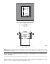
DRAIN
5
3
/4
″ (146mm)
3
/8-IN. HEX NUT
& WASHER (4)
REQD PER ROD
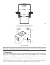
VENT
COMBUSTION-AIR PIPE
(DIRECT VENT/2-PIPE
APPLICATION,ALL SIZES)
COMBUSTION-AIR INTAKE
(NON-DIRECT VENT/1-PIPE
APPLICATION)
3-IN. MINIMUM CLEARANCE TO
COMBUSTION-AIR INTAKE IS REQUIRED
(NON-DIRECT VENT/1-PIPE
APPLICATION,)
—21—