


4. Follow the lighting instructions. Place the appliance being inspected in operation. Adjust thermostat so appliance shall operate continuously.
5. Test for draft hood equipped appliance spillage at the draft hood relief opening after 5 minutes of main burner operation. Use the flame of
a match or candle.
6. After it has been determined that each appliance connected to the venting system properly vents when tested as outlined above, return doors,
windows, exhaust fans, fireplace dampers, and any other gas-burning appliance to their previous conditions of use.
7. If improper venting is observed during any of above tests, the venting system must be corrected.
Vent system or vent connectors may need to be resized. For any other appliances when resizing vent systems or vent connectors, system or
connector must be sized to approach minimum size as determined using appropriate table found in the NFGC or NSCNGPIC.
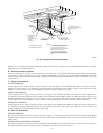
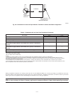
B. Combustion-Air and Vent Piping
GENERAL
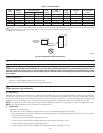
Combustion-air and vent pipe, fittings, primers, and solvents must conform to American National Standards Institute (ANSI) standards and
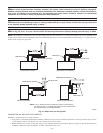
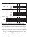
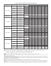
American Society for Testing and Materials (ASTM) standards. See Table 6 for approved materials for use in the U.S.A. See Table 7 for maximum
pipe lengths and Fig. 39, 40, 41, 42, and 43 for exterior piping arrangements.
In Canada, construct all combustion-air and vent pipes for this unit of CSA or ULC certified schedule-40 PVC, PVC-DWV or ABS-DWV pipe
and pipe cement. SDR pipe is NOT approved in Canada.
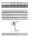
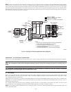
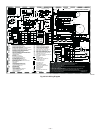
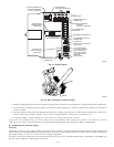
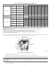
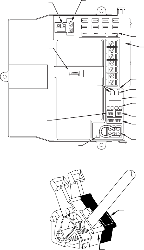
Fig. 31—Control Center
A99097
W2
COM
24V
W/W1 Y/Y2
RG
HUM
HOT SURFACE
IGNITOR CONNECTOR
EAC-ELECTRONIC AIR
CLEANER TERMINALS
(115-VAC 1 AMP MAX)
115-V
CONNECTORS
24-V THERMOSTAT
TERMINALS
PRESSURE SWITCH
CONNECTOR
HUM-HUMIDIFIER
TERMINAL
(24-VAC 0.5 AMP MAX)
TRANSFORMER
24-V CONNECTORS
3-AMP FUSE
STATUS AND DIAGNOSTIC
LED LIGHTS
AIR CONDITIONING
(A/C) SETUP SWITCH
SETUP SWITCHES
(SW) AND BLOWER
OFF DELAY SETUP
SWITCHES
MODEL PLUG
COMMUNICATION
CONNECTOR
CONTINUOUS
FAN (CF) SETUP
SWITCHES
MAIN BLOWER
CONTROL WIRE
CONNECTOR
DEHUMIDIFIER (DEHUM)
CONNECTOR
DEHUMIDIFY ENABLE (DE)
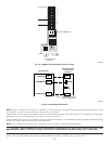
Fig. 32—EAC Terminals on Control Center
A93053
EAC2
EAC1
—29—