


8. Electronic Air Cleaner—The EAC-1 terminal is energized whenever blower operates.
9. Inducer speed operation—If cycle starts in low heat, inducer speed reduces slightly after the flame sense. If cycle starts in high heat,
inducer speed increases 15 sec after flame sense. The reduction in speed in low heat is to optimize combustion for maximum efficiency.
10. Call for heat terminated—When the call for heat is satisfied, the R-W/W1 signal is terminated, de-energizing gas valve (stopping gas flow
to burners), and HUM terminal is de-energized.
a. R-W/W1 signal terminated with R-Y/Y2 and R-G still present—The blower changes its speed to cooling RPM.
b. R-W/W1 with R-Y/Y2 and R-G signals terminated—The blower continues to operate completing a normal heating blower off delay.
11. Post purge—The inducer continues operating for 15 sec after gas valve is de-energized.
B. Two-Speed Applications
For details on 2-speed heat pump applications, refer to Fig. 52.
PROCEDURE 7—CONTINUOUS FAN MODE
1. Operating with continuous fan only
a. Call for continuous fan—The thermostat closes R-G circuit.
b. Blower on—The blower starts immediately.
NOTE: The blower starts at approximately 400-500 RPM. After 20 sec, the motor is turned off for 1/10 of a sec where a coast down calibration
is done to evaluate resistance of the conditioned air duct system. The microprocessor then determines blower RPM required to provide proper
airflow for heating mode.
NOTE: The continuous fan speed is the same as low-heat speed unless it is field adjusted to another desired airflow. See Continuous Fan Setup
Switches section. There is also a chart on wiring diagram. (See Fig. 30.)
c. Electronic Air Cleaner—The EAC-1 terminal is energized whenever blower operates, regardless of operating mode.
2. Operating with continuous fan (R-G) and call for heat (R-W/W1) is received—Same as heat pump mode except blower on delay is 10
sec less than heat mode. After call for heat (R-W/W1) is terminated, the blower remains operating at low-heat speed for selected blower
off delay before resuming continuous fan speed.
3. Operating with continuous fan (R-G) and call for cooling (R-Y/Y2) is received— See Cooling Mode section. After call for cooling
(R-Y/Y2) is terminated, the blower remains operating at cooling speed for 90 sec before resuming continuous fan speed.
PROCEDURE 8—COMPONENT TEST
All components are functionally operated except gas valve with component test feature.
This feature helps diagnose a system problem in case of a component failure.
NOTE: Setup switch SW-1 MUST be in OFF position or Fault Code 22 (setup error) will occur.
NOTE: NO thermostat signal may be present at control center, and all blower time delay off periods must be completed.
To initiate component test feature, proceed with the following:
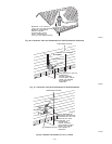
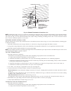
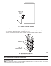
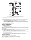
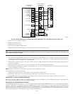
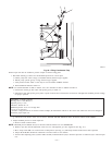
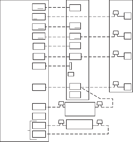
Fig. 51—Wiring Schematic for 2-Speed Application with Thermidistat Control
A01473
HUMIDIFIER
SOLENOID VALVE
(24 VAC)
O/W2
Y1/W2
W/W1
G
R
W2
THERMIDISTAT™
CONTROL
VARIABLE-SPEED
CONDENSING
FURNACE
2-SPEED
AIR CONDITIONER
W/W1
G
C
Y2
R
Y1
C
DHUM
HUM
B
S1
S2
Y/Y2
R
DEHUM
DE
COM
HUM
HEAT STAGE 2
HEAT STAGE 1
COOL STAGE 1
COOL STAGE 2
FAN
24 VAC HOT
24 VAC COMM
DEHUMIDIFY
HUMIDIFY
N/A
OUTDOOR
SENSOR
CONNECTION
Y/Y2
OUTDOOR
SENSOR
—46—