


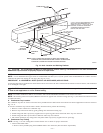
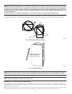
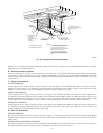
CAUTION: The entire length of furnace MUST be supported when furnace is used in a horizontal position to ensure
proper draining. When suspended, bottom brace supports sides and center blower shelf. When unit is supported from the
ground, blocks or pad should support sides and center blower shelf area.
PROCEDURE 4—AIR DUCTS
A. General Requirements
The duct system should be designed and sized according to accepted national standards such as those published by: Air Conditioning Contractors
Association (ACCA), Sheet Metal and Air Conditioning Contractors National Association (SMACNA) or American Society of Heating,
Refrigerating and Air Conditioning Engineers (ASHRAE), or consult The Air Systems Design Guidelines reference tables available from your
local distributor. The duct system should be sized to handle the required system design CFM at the design static pressure.
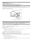
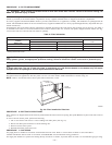
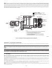
When a furnace is installed so that the supply ducts carry air to areas outside the space containing the furnace, the return air must also be handled
by a duct(s) sealed to the furnace casing and terminating outside the space containing the furnace.
Secure ductwork with proper fasteners for type of ductwork used. Seal supply- and return-duct connections to furnace with code approved tape
or duct sealer.
Flexible connections should be used between ductwork and furnace to prevent transmission of vibration. Ductwork passing through unconditioned
space should be insulated to enhance system performance. When air conditioning is used, a vapor barrier is recommended.
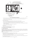
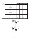
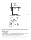
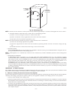
Fig. 20—Furnace, Plenum, and Coil Assembly or
Coil Box Installed on a Combustible Floor
A96284
CD5 OR CK5
COIL ASSEMBLY
OR KCAKC
COIL BOX
FURNACE
SHEET METAL
PLENUM
FLOOR
OPENING
COMBUSTIBLE
FLOORING
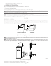
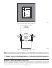
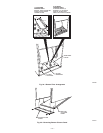
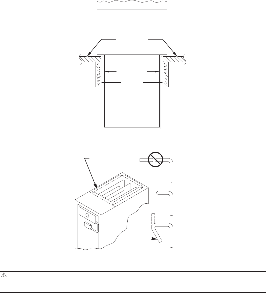
Fig. 21—Duct Flanges
A93029
NO
YES
YES
PERFORATED
DISCHARGE DUCT
FLANGE
210 DEG.
MIN
—20—