


NOTE: The CF switches are factory set to provide continuous fan airflow equal to low-heat mode.
5. Replace main furnace door and blower access panel.
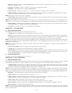
C. Setup Switches (SW)
The control center has 8 setup switches that may be set to meet the application requirements. Position these setup switches for the appropriate
requirement.
1. Remove main furnace door and blower access panel.
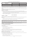
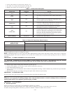
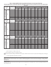
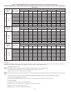
Table 9—Air Conditioning (A/C) Airflow Switch Position
AIR
CONDITIONER
(TONS)
CFM AIRFLOW
A/C SETUP
SWITCH POSITION
ALLOWABLE FURNACE MODEL SETUP
A/C-1 A/C-2 A/C-3 042040 042060 042080 060080 060100 060120
Default
1200 or
2000
OFF OFF OFF
3 Tons
1200 CFM
3 Tons
2000 CFM
3 Tons
1200 CFM
5 Tons
2000 CFM
5 Tons
2000 CFM
5 Tons
2000 CFM
1–1/2 600 ON OFF OFF X X X — — —
2 800 OFF ON OFF X X X X X X
2–1/2 1000 ON ON OFF X X X X X X
3 1200 OFF OFF ON X X X X X X
3–1/2 1400 ON OFF ON X X X X X X
4 1600 OFF ON ON — — — X X X
5 2000 ON ON ON — — — X X X
X–Indicates allowable selection.
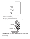
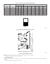
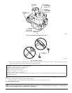
Fig. 53—Example of Setup Switch in OFF Position
A95198
1
OFF
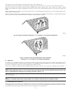
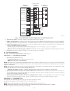
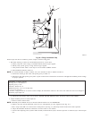
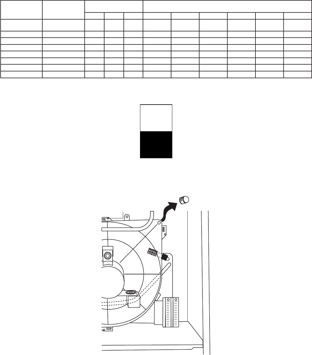
Fig. 54—Inducer Housing Drain Tube
A99118
—49—