


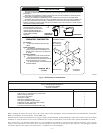
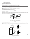
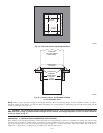

CAUTION: The condensate trap MUST be installed below furnace. See Fig. 4 for dimensions. The drain connection to
condensate trap must also be properly sloped to an open drain.
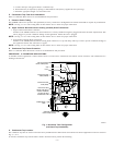
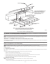
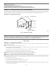
NOTE: Combustion-air and vent pipes are restricted to a minimum length of 5 ft. (See Table 6.)
NOTE: A 12-in. minimum offset pipe section is recommended with short (5 to 8 ft) vent systems. This recommendation is to reduce excessive
condensate droplets from exiting the vent pipe. (See Fig. 10 or 32.)
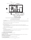
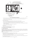
PROCEDURE 5—HORIZONTAL RIGHT (SUPPLY-AIR DISCHARGE) APPLICATIONS
A horizontal right furnace application is where furnace blower is located to the left of combustion and controls section of furnace, and conditioned
air is discharged to the right.
CAUTION:
Local codes may require a drain pan under entire furnace and condensate trap when a condensing furnace
is used in attic application or over a finished ceiling.
NOTE: In Canada, installations shall be in accordance with current NSCNGPIC Installation Codes and/or local codes.
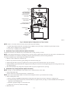
NOTE: The auxiliary junction box (J-Box) MUST be relocated to opposite side of furnace casing. (See Fig. 11.) See Electrical Connection section
for J-Box relocation.
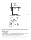
A. Condensate Trap Location
The condensate trap must be removed from the factory-installed blower shelf location and relocated in selected application location as shown in
Fig. 2 or 11.
To relocate condensate trap from the blower shelf to desired location, perform the following:
1. Remove 3 tubes connected to condensate trap.
2. Remove trap from blower shelf by gently pushing tabs inward and rotating trap
3. Install casing hole filler cap (factory-supplied in loose parts bag) into blower shelf hole where trap was removed.
4. Install casing hole filler cap into blower shelf hole where trap was removed.
5. Fill unused condensate trap casing holes with plastic filler caps (factory-supplied in loose parts bag).
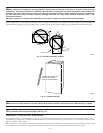
B. Condensate Trap Tubing
NOTE: See Fig. 11 or tube routing label on main furnace door to check for proper connections.
1. Collector Box Drain Tube:
a. Remove factory-installed plug from LOWER collector box drain tube (blue and white striped label).
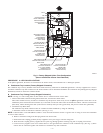
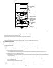
Fig. 10—Attic Location and Working Platform
A93031
COMBUSTION - AIR
INTAKE
VENT
MANUAL
SHUTOFF
GAS VALVE
SEDIMENT
TRAP
CONDENSATE
TRAP
DRAIN
ACCESS OPENING
FOR TRAP
30″ (762 mm)MIN
WORK AREA
A 12-IN. (305 mm) MIN HORIZONTAL PIPE
SECTION IS RECOMMENDED WITH
SHORT (5 TO 8 FT / 1.5 TO 2.4 M) VENT
SYSTEMS TO REDUCE EXCESSIVE
CONDENSATE DROPLETS FROM
EXITING THE VENT PIPE.
5
3
/
4
″ (146 mm)
NOTE: LOCAL CODES MAY REQUIRE A DRAIN PAN UNDER THE
FURNACE AND CONDENSATE TRAP WHEN A CONDENSING
FURNACE IS INSTALLED ABOVE FINISHED CEILINGS.
—13—