


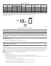
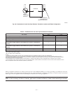
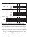
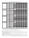
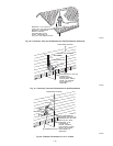
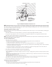
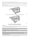
NOTE: Do not count elbows or pipe sections in terminations or within furnace. See shaded areas in Fig. 40, 41, 42, 43, and 44.
EXAMPLE: An 042080 size furnace located in Indianapolis, elevation 650 ft above sea level, could be installed in an application requiring
3 elbows and 17 ft of vent pipe, along with 5 elbows and 16 ft of combustion-air pipe. Table 7 indicates this application would allow a
1-1/2-in. diameter vent pipe, but require a 2-in. diameter combustion air pipe (1-1/2-in. pipe is good for 20 ft with 3 elbows, but only 10
ft with 5 elbows). Therefore, 2-in. diameter pipe must be used for both vent and combustion-air pipes since larger required diameter must
always be used for both pipes. If same installation were in Albuquerque, elevation 5250 ft above sea level, installation would require 2-in.
vent pipe and combustion-air pipe. At 5001- to 6000-ft elevation, 1-1/2-in. pipe is not allowed with 5 elbows, but 2-in. pipe is good for
68 ft with 5 elbows.
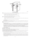
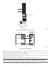
COMBUSTION-AIR AND VENT PIPE ATTACHMENT
NOTE: All pipe joints must be watertight except attachment of combustion-air pipe to inlet housing connection, since it may be necessary to
remove pipe for servicing.
1. Attach combustion-air pipe to furnace as follows:
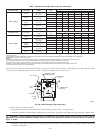
a. Determine location of combustion-air intake pipe connection to combustion-air intake housing as shown in Fig. 36 for application.
b. Reposition combustion-air intake housing plug fitting in appropriate unused intake housing connection.
c. If required, insert perforated disk assembly (factory-supplied in loose parts bag) in intake housing where combustion-air intake pipe will
be connected. If half disk set is required, install with shoulder of disk against stop in combustion-air inlet.
d. Install pipe support (factory-supplied in loose parts bag) into selected furnace casing combustion-air pipe hole. Pipe support should be
positioned at bottom of casing hole.
e. Insert 2-in. diameter pipe into intake housing.
f. Install casing hole filler cap (factory-supplied in loose parts bag) in unused combustion-air pipe casing hole.
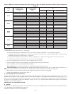
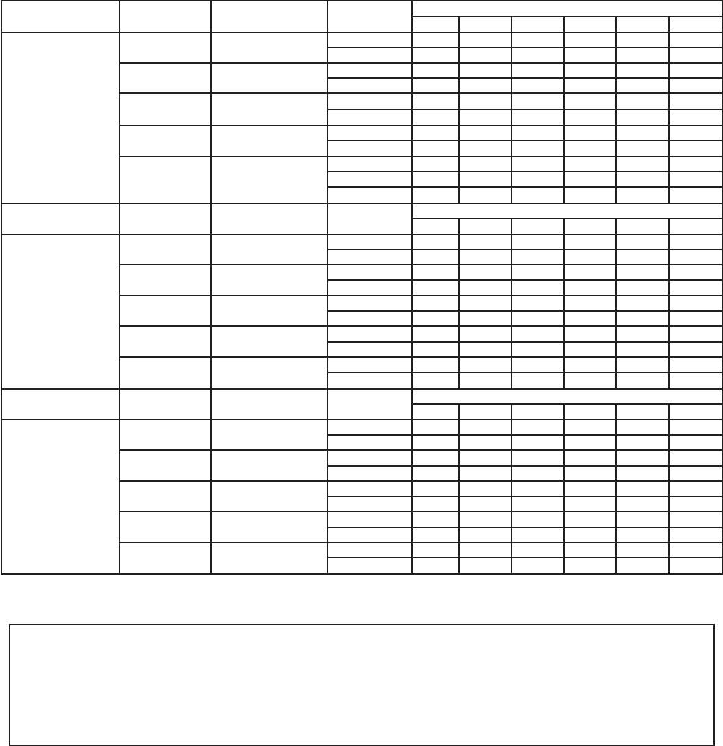
Table 7—Maximum Allowable Pipe Length (ft)
ALTITUDE (FT) UNIT SIZE
TERMINATION
TYPE
PIPE DIA
(IN.)*
NUMBER OF 90° ELBOWS
123456
0 to 2000
042040
2 Pipe or 2-in
Concentric
1-1/2 50 45 40 35 30 25
2 707070707070
042060
2 Pipe or 2-in
Concentric
1-1/2 50 45 40 35 30 25
2 707070707070
042080
060080
2 Pipe or 2-in
Concentric
1-1/2 30 25 20 15 10 5
2 707070707070
060100
2 Pipe or 2-in
Concentric
2 454035302520
2-1/2 70 70 70 70 70 70
060120
2 Pipe or 3-in.
Concentric
2-1/2 10 NA NA NA NA NA
3 3530 15NANANA
3† 70 70 70 70 70 70
ALTITUDE (FT) UNIT SIZE
TERMINATION
TYPE
PIPE DIA
(IN.)*
NUMBER OF 90° ELBOWS
123456
2001 to 3000
042040
2 Pipe or 2-in
Concentric
1–1/2 45 40 35 30 25 20
2 707070707070
042060
2 Pipe or 2-in
Concentric
1–1/2 45 40 35 30 25 20
2 707070707070
042080
060080
2 Pipe or 2-in
Concentric
1–1/2 26 21 16 11 6 NA
2 707070707070
060100
2 Pipe or 2-in
Concentric
2 403530252015
2–1/2 70 70 70 70 70 70
060120
2 Pipe or 3-in.
Concentric
3 3126 12NANANA
3† 63 62 62 61 61 61
ALTITUDE (FT) UNIT SIZE
TERMINATION
TYPE
PIPE DIA
(IN.)*
NUMBER OF 90° ELBOWS
123456
3001 to 4000
042040
2 Pipe or 2-in
Concentric
1-1/2 42 37 32 27 22 17
2 707070707070
042060
2 Pipe or 2-in
Concentric
1-1/2 42 37 32 27 22 17
2 707070707070
042080
060080
2 Pipe or 2-in
Concentric
1-1/2 25 20 15 10 5 NA
2 707070707070
060100
2 Pipe or 2-in
Concentric
2 383328231813
2-1/2 70 70 70 70 70 70
060120
2 Pipe or 3-in.
Concentric
3 2924 10NANANA
3† 59 59 58 57 57 56
See notes at end of table.
—34—