


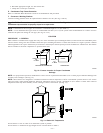

c. Install cap and clamp on UPPER inducer housing drain connection where molded drain tube was removed.
d. Use inducer housing drain tube (violet label and factory-supplied in loose parts bag) to connect LOWER inducer housing drain
connection to the condensate trap.
e. Connect inducer housing drain connection to condensate trap.
(1.) Condensate Trap Located on Left Side of Casing
Determine appropriate length and cut.
Connect tube to condensate trap.
Clamp tube to prevent any condensate leakage.
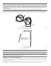
(2.) Condensate Trap Located on Right Side of Casing
Route inducer housing drain tube (violet label) directly from inducer housing to condensate trap.
Determine appropriate length and cut.
Connect tube to condensate trap.
Clamp tube to prevent any condensate leakage.
3. Relief Port Tube
Refer to Pressure Switch Tubing section for connection procedure.
C. Condensate Trap Field Drain Attachment
Refer to Condensate Drain section for recommendations and procedures.
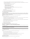
D. Pressure Switch Tubing
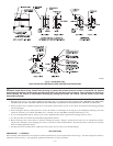
One collector box pressure tube (pink label) is factory connected to the pressure switch for use when furnace is installed in UPFLOW or
HORIZONTAL LEFT applications. This tube MUST be disconnected and used for the condensate trap relief port tube. The other collector box
pressure tube (green label) which was factory connected to the condensate trap relief port connection MUST be connected to the pressure switch
in DOWNFLOW or HORIZONTAL RIGHT applications.
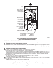
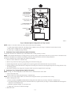
NOTE: See Fig. 7 or 8 or tube routing label on main furnace door to check for proper connections.
Relocate tubes as described below.
1. Disconnect collector box pressure tube (pink label) attached to pressure switch.
2. Extend collector box pressure tube (green label) which was previously connected to condensate trap relief port connection by splicing to
small diameter tube (factory-supplied in loose parts bag).
3. Connect collector box pressure tube (green label) to pressure switch connection labeled COLLECTOR BOX.
4. Extend collector box pressure tube (pink label) which was previously connected to pressure switch by splicing to remaining small diameter
tube (factory-supplied in loose parts bag).
5. Route this extended tube (pink label) to condensate trap relief port connection.
6. Determine appropriate length, cut, and connect tube.
7. Clamp tube to relief port connection.
E. Condensate Trap Freeze Protection
Refer to Condensate Drain Protection section for recommendations and procedures.
PROCEDURE 4—HORIZONTAL LEFT (SUPPLY-AIR DISCHARGE) APPLICATIONS
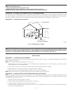
A horizontal left furnace application is where furnace blower is located to the right of combustion and controls section of furnace, and conditioned
air is discharged to the left.
CAUTION: Local codes may require a drain pan under entire furnace and condensate trap when a condensing furnace
is used in an attic application or over a finished ceiling.
NOTE: In Canada, installations shall be in accordance with current NSCNGPIC and/or local codes.
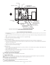
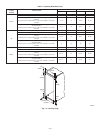
A. Condensate Trap Location
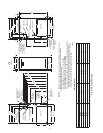
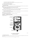
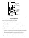
The condensate trap must be removed from the factory-installed blower shelf location and relocated in selected application location as shown in
Fig.2or9.
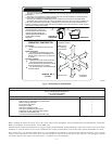
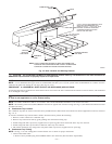
To relocate condensate trap from the blower shelf to desired location, perform the following:
1. Remove 3 tubes connected to condensate trap.
2. Remove trap from blower shelf by gently pushing tabs inward and rotating trap.
3. Install casing hole filler cap (factory-supplied in loose parts bag) into blower shelf hole where trap was removed.
4. Install casing hole filler cap into blower shelf hole where trap was removed.
5. Fill unused condensate trap casing holes with plastic filler caps (factory-supplied in loose parts bag).
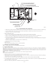
B. Condensate Trap Tubing
NOTE: See Fig. 9 or tube routing label on main furnace door to check for proper connections.
1. Collector Box Drain Tube
—11—