


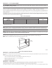
PROCEDURE 5—FILTER ARRANGEMENT
WARNING: Never operate unit without a filter or with filter access door removed. Failure to follow this warning can
cause fire, personal injury, or death.
The air filter arrangement will vary due to application, furnace orientation, and filter type. The filter may be installed in an external Filter/Media
cabinet (if provided) or the furnace blower compartment. Factory supplied washable filters are shipped in the blower compartment.
If a factory-supplied external Filter/Media cabinet is provided, instructions for its application, assembly, and installation are packaged with the
cabinet. The Filter/Media cabinet can be used with the factory-supplied washable filter or a factory-specified high-efficiency disposable filter (see
cabinet instructions).
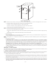
If installing the filter in the furnace blower compartment, determine location for filter and relocate filter retaining wire if necessary. See Table 2
to determine correct filter size for desired filter location. Table 2 indicates filter size, location, and quantity shipped with this furnace. See Fig.
2 for location and size of bottom and side return-air openings.
CAUTION: Use care when cutting support rods in filters to protect against flying pieces and sharp rod ends. Wear
safety glasses, gloves, and appropriate protective clothing. Failure to follow this caution could result in personal injury.
CAUTION: For airflow requirements above 1800 CFM, see Air Delivery table in Product Data literature for specific use
of single side inlets. The use of both side inlets, a combination of 1 side and the bottom, or the bottom only will ensure
adequate return air openings for airflow requirements above 1800 CFM.
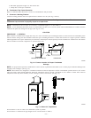
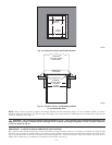
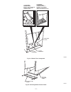
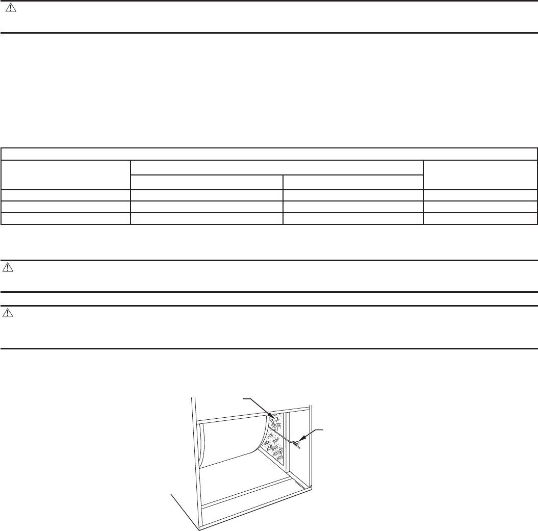
NOTE: Side return-air openings can ONLY be used in UPFLOW configurations. Install filter(s) as shown in Fig. 23.
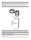
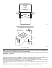
For bottom return-air applications, filter may need to be cut to fit some furnace widths. Install filter as shown in Fig. 24.
NOTE: Remove and discard bottom closure panel when bottom inlet is used.
PROCEDURE 6—BOTTOM CLOSURE PANEL
These furnaces are shipped with bottom enclosure panel installed in bottom return-air opening. This panel MUST be in place when side return air
is used.
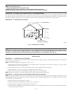
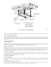
To remove bottom closure panel, perform the following:
1. Tilt or raise furnace and remove 2 screws holding front filler panel. (See Fig. 25.)
2. Rotate front filler panel downward to release holding tabs.
3. Remove bottom closure panel.
4. Reinstall front filler panel and screws.
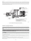
PROCEDURE 7—GAS PIPING
Gas piping must be installed in accordance with national and local codes. Refer to current edition of NFGC in the United States.
Canadian installations must be made in accordance with NSCNGPIC and all authorities having jurisdiction.
Gas supply line should be a separate line running directly from meter to furnace, if possible. Refer to Table 3 for recommended gas pipe sizing.
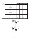
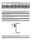
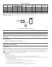
Table 2—Filter Information
AIR FILTER LOCATED IN BLOWER COMPARTMENT
FURNACE
CASING
WIDTH (IN.)
FILTER SIZE (IN.)*
FILTER
TYPE
Side Return Bottom Return
17-1/2 (1) 16 X 25 X 1† (1) 16 X 25 X 1† Cleanable
21 (1) 16 X 25 X 1 (1) 20 X 25 X 1† Cleanable
24-1/2 (1 or 2) 16 X 25 X 1 (1) 24 X 25 X 1† Cleanable
* Filters may be field modified by cutting filter material and support rods (3) in filters. Alternate sizes and additional filters may be ordered from your dealer.
† Factory-provided with furnace.
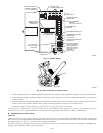
Fig. 23—Filter Installed for Side Inlet
A93045
FILTER
RETAINE
R
WASHABLE
FILTER
—22—