


– 175 –
INSTALLATION MANUAL
Network Adapter for Air Conditioner
Use for Indoor Unit Only
MODEL : TCB-PCNT20E
[For Installation Professionals]
• Thank you for purchasing the parts sold separately for TOSHIBA package air conditioner.
• Before installation work, please read this manual thoroughly and install the products correctly.
• Ensure that all Local, National and International regulations are satisfied.
• Read this “CAUTION SAFETY” carefully before Installation.
• The precautions described below include the important items regarding safety.
CAUTIONS for SAFETY
WARNING
• Ask an authorized dealer or qualified installation professional to install/maintain the air conditioner.
Inappropriate installation may result in water leakage, electric shock or fire.
• Turn off the main power supply switch or breaker before attempting any electrical work.
Make sure all power switches are off. Failure to do so may cause electric shock.
• Connect the connecting cable correctly.
If the connecting cable is connected in a wrong way, electric parts may be damaged.
• When moving the air conditioner for the installation into another place, be very careful not to enter any gaseous
matter other than the specified refrigerant into the refrigeration cycle.
If air or any other gas is mixed in the refrigerant, the gas pressure in the refrigeration cycle becomes abnormally high and
it may resultingly causes pipe burst and injuries on persons.
• Do not modify this unit by removing any of the safety guards or by by-passing any of the safety interlock switches.
• Exposure of unit to water or other moisture before installation may cause a short-circuit of electrical parts.
Do not store it in a wet basement or expose to rain or water.
CAUTION
• Using the specified cables, surely so that the external force of the cable is not transmitted to the terminal connecting
section, otherwise disconnection, heating, or fire may be caused.
• Do not apply an excessive force on the board body, otherwise bending, separation, or disconnection generates resulted
in heating or fire.
• After installation work, execute a test run to confirm there is no trouble.
And also ask the customers to keep this Manual by themselves.
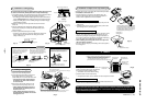
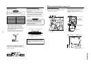
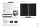
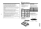
Components
Part name
P.C. board
Relay terminal block
Relay cable (A)
Relay cable (B)
Installation Manual
Spacer (A)
Spacer (B)
Spacer (C)
Screws to fix terminal block
Transformer cover
Transformer base
Transformer
Screws to fix transformer
Screws to assemble transformer cover
Screws to fix transformer base
Bundling band
Q’ty
1
1
1
1
1
2
1
3
2
1
1
1
2
2
2
3
Description
P.C. board corresponded to the network
2P (X, Y) terminal block for relay
For connection of adapter board with X, Y relay terminal block (Red connector)
For connection of adapter board with remote controller terminal block (Blue connector)
This manual
For fixing the adapter P.C. board
(Used for other types than 4-way cassette type)
For fixing the adapter P.C. board
(Used for other types than 4-way cassette type)
For fixing the adapter P.C. board
(Used for 4-way cassette type)
For fixing the relay terminal block (M4 x 14 )
Used to store transformer (For 4-way cassette type)
Used to store transformer (For 4-way cassette type)
For supplying power to adapter
For fixing transformer (M3 x 6 )
For assembling transformer cover (M4 x 6 for 4-way)
For fixing transformer base (M4 x 10 for 4-way)
Used to process cables so that they are not caught in.
10mm
18mm
10mm
A
B
C
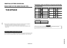
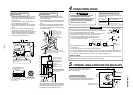
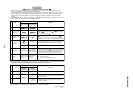
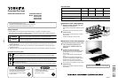
Combination List of Adapter Parts
1
2
3
4
5
6
7
For 4-way type
3 spacers (C) for installing P.C. board
M3 x 6 B tight screw (2 pcs.)
M4 x 6 tapping screws (2 pcs.)
M4 x 10 plus tight screws (2 pcs.)
M4 x 14 tapping tight screws (2 pcs.)
Connector, red color, lead length : 600L
Connector, blue color, lead length : 600L
Parts
Adapter P.C. board
Transformer
For assembling transformer cover
For fixing transformer base
XY terminal block
Adapter P.C. board to XY terminal block
Adapter P.C. board to AB terminal block
For Concealed duct type
2 spacers (A) for installing P.C. board
1 spacer (B) for installing P.C. board
M3 x 6 B tight screw (2 pcs.)
———
———
M4 x 14 tapping tight screws (2 pcs.)
Connector, red color, lead length : 600L
Connector, blue color, lead length : 600L
* Spacer (A) for installing P.C. board : Spacer to be mounted by using the hole on the P.C. board.
(For other types than 4-way cassette type)
Spacer (B) for installing P.C. board : Spacer to be mounted by pinching it in the P.C. board.
(For other types than 4-way cassette type)
Spacer (C) for installing P.C. board : Spacer to be mounted by using the hole on the P.C. board for 4-way cassette type.
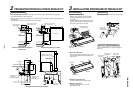
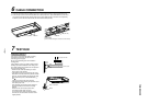
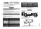
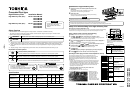
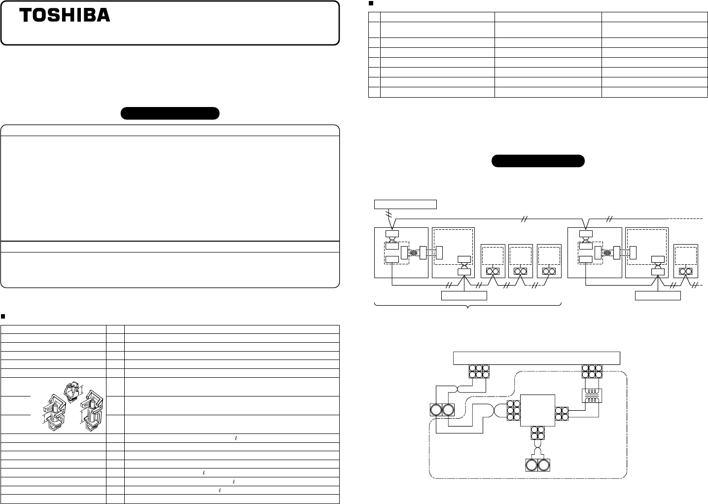
Connection of Cables
1. Connection of network cables
• Attach one network adapter to a group of one group controlling (including one unit).
Connect the network adapter to any one of the indoor units in the group control.
X Y
Central remote controller
Remote controller
Non polarity cable
Connectable indoor units per group : Up to 8 units (In case of 1-remote controller system
*
)
*
In case of 2-remote controllers system, up to 7 indoor units are allowable to be connected.
Non polarity cable Non polarity cable
Non polarity cable
A B
Indoor
control
P.C.board
Indoor unit
Indoor
unit
Indoor unit
controll
P.C.board
A B
Indoor
control
P.C .boar d
Indoor unit
A B
Indoor
control
P.C.board
Indoor unit
Remote controller
1 2
CN03
CN02
CN041 CN041
2
1
3
1
1 3
3
1
1 3
A B
X Y
AB
Indoor
control
P.C .boar d
Indoor unit
Indoor
unit
Indoor unit
controll
P.C.board
1 2
CN03
CN02
CN01 CN01
CN309CN309
2
1
3
1
1 3
3
1
1 3
A B
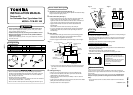
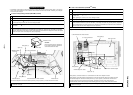
2. Cabling diagram of indoor control P.C. board
• For details, see the installation procedure for individual model.
1
1
2
2
A B
1
1
2
2
3
2
3
2
1 1
3
3
1
1
2
2
3
3
2 2
1 1
X Y
BlackBlack
White
Black
Gray Gray
CN01 (White)
CN02 (Blue)
CN041 (Blue) CN309 (Yellow)
CN03 (Red)
Network connection terminal block
Network
adapter
P.C. board
Indoor control P.C. board
Terminal block
for connecting
remote controller
Power
supply
transformer
• The enclosed section with the chain line includes the attached parts.
• There is no polarity for cabling to the terminal blocks, A, B and X, Y.
• Arrange the total cable length of the remote controller cable and the inter-unit cable of the remote controller within 400m.
TCB-PCNT20E