


– 126 –
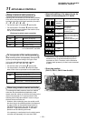
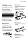
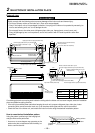
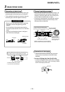
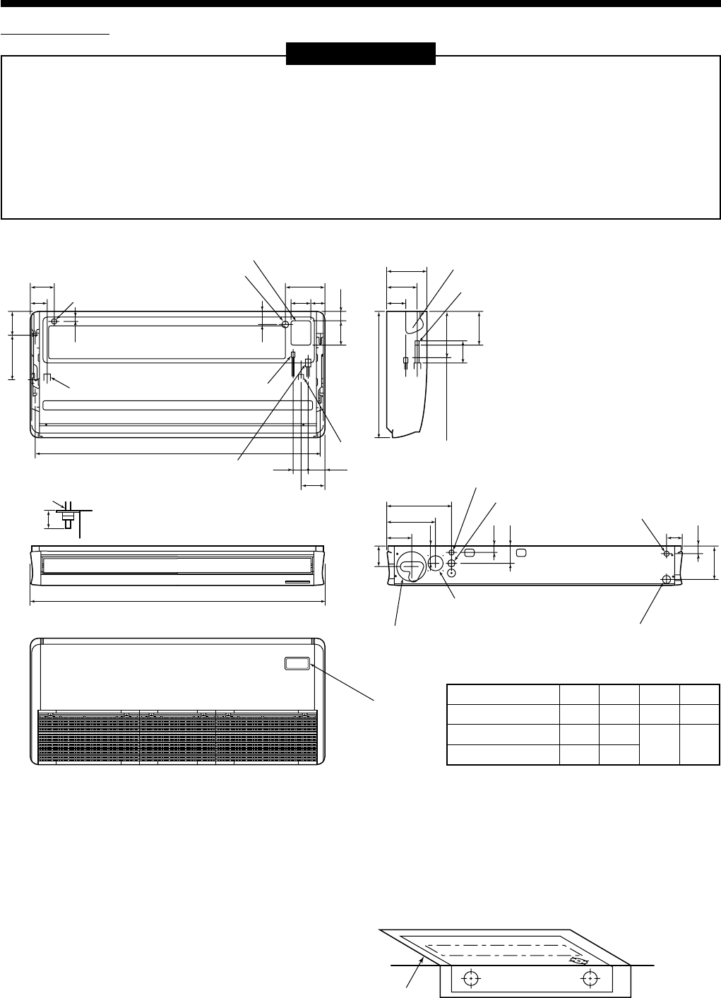
RAV-SM561, 801CT-E
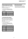
RAV-SM1101, 1401CT-E
External view
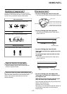
REQUIREMENT
Strictly comply with the following rules to prevent damage of the indoor units and human injury.
• Do not put a heavy article on the indoor unit. (Even units are packaged)
• Carry in the indoor unit as it is packaged if possible. If carrying in the indoor unit unpacked by necessity, be
sure to use buffering cloth, etc. to not damage the unit.
• Do not apply force to the other parts (refrigerant pipe, drain pan, foamed parts, or resin parts, etc.).
• Carry the package by two or more persons, and do not bundle it with PP band at positions other than
specified.
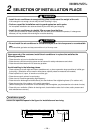
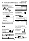
Considering pipe/wire connecting work inside the ceiling after the indoor unit has been hanged, select an installation
place and determine piping direction.
• If the ceiling has already been set before hanging the main unit, prepare refrigerant pipe, drain pipe, indoor
connecting wire, remote controller cord, etc. up to the place where pipe and wire can be connected.
• Check the size of the indoor unit, and match the indoor unit size using the attached installation pattern.
Upper pipe draw-out port (Knockout hole)
Power supply cable take-in port (Knockout)
Remote controller cable take- in port
(Knockout hole)
Left drain size
B (Hanging position)
A
Refrigerant pipe
(Liquid side ØC)
Refrigerant pipe (Gas side ØD)
Drain pipe connecting port
Drain port VP20
(Inner dia. Ø26, hose attached)
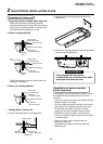
Pipe draw-out port (Knockout hole)
200 (Liquid pipe)
216 (Gas pipe)
Power supply cable take-in port (Knockout hole)
Remote controller cable take- in port
Remote controller cable take- in port
(Knockout hole)
Outside air take-in port
(Duct sold separately)(Knockout hole Ø92)
Pipe hole on wall (Ø100 hole)
Drain left pipe draw-out port (Knockout hole)
Wireless sensor
mounting section
561CT
801CT
1101CT to 1401CT
Model name A B C D
910
1180
1595
855
1125
1540
Ø6.4 Ø12.7
Ø9.5 Ø15.9
(Hanging position)
84
135 84
262
347
171
145
32
32
90
92
53
70
130
680
41
114
50
170320
128
110
146
75 97
76
216
167
105
210
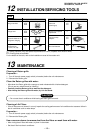
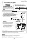
Hanging bolt
Ceiling surface
Unit
Within
50
How to use attached installation pattern
Using the pattern, positioning of the hanging bolt
and pipe hole can be performed.
* As an error to some degree may generate on the
pattern size due to temperature and humidity, be
sure to confirm the size.
Wall face
Ceiling surface
Installation
pattern
2
SELECTION OF INSTALLATION PLACE