– 162 –
INSTALLATION MANUAL
Remote Controller Wireless Kit
RBC-AX22CE
Thank you very much for purchasing TOSHIBA Remote Controller for Air Conditioner.
Please read this owner's manual carefully before using your Remote Controller for Air
Conditioner.
• Be sure to obtain the “Owner’s manual” and “Installation manual” from constructor (or
dealer).
Request to constructor or dealer
Please clearly explain the contents of the Owner’s manual and hand over it.
Accessory parts
No.
1
2
3
Accessory
Sensor unit
Remote controller
Remote controller holder
Q’ty
1
1
1
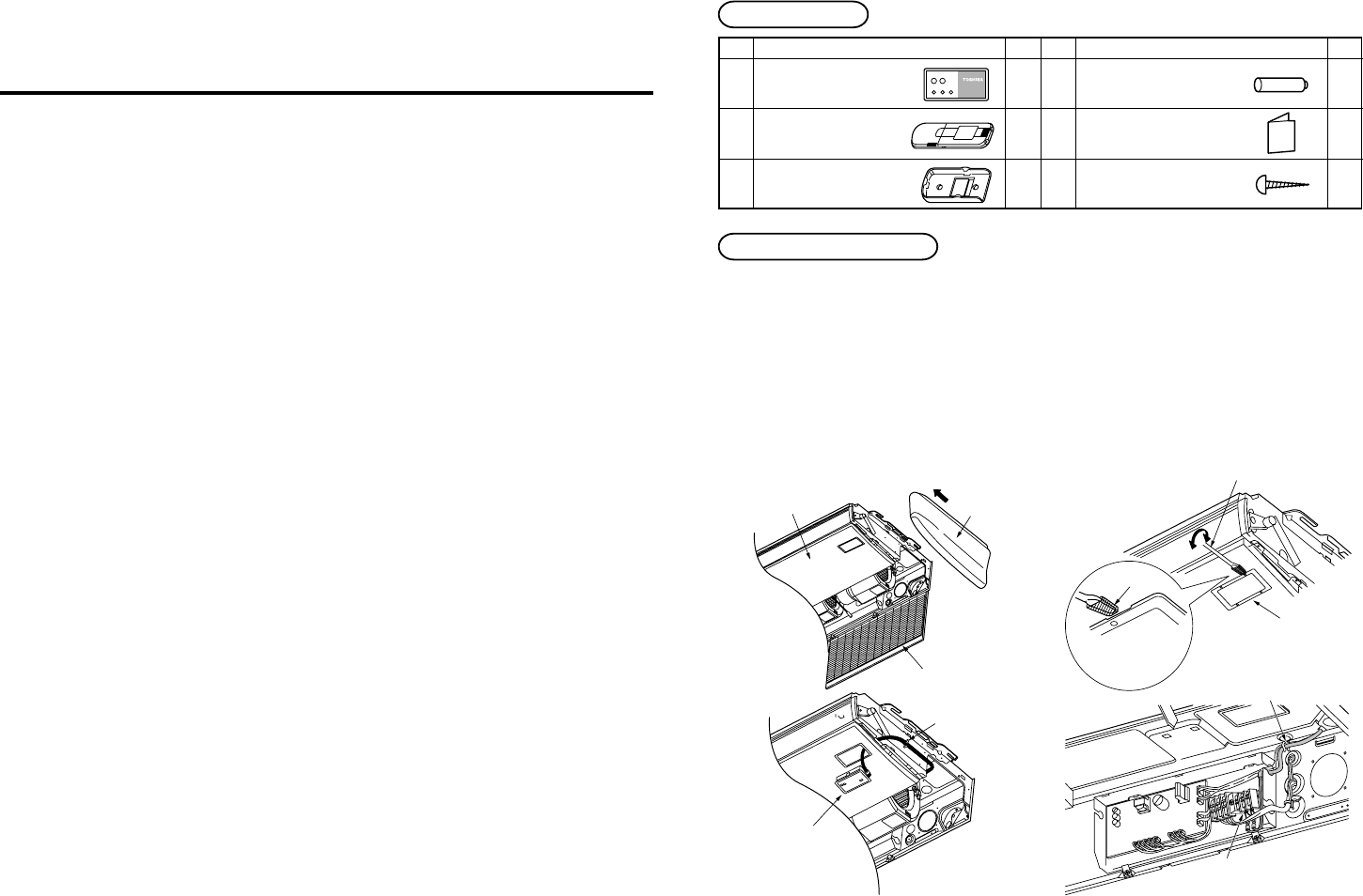
Installation of sensor unit
1. Open the suction grille, remove a screw, move the side panel toward you (direction of arrow), and
then remove the side panel. (Fig. A)
2. Lap the end of flat head screw driver with vinyl tape, and forcedly insert it into the groove at the
side under circle mark on the cover. (Be careful not to damage the panel.) (Fig. B)
3. Pass the lead wire through the panel, and install the sensor unit to the panel hole.
(Projection of the sensor unit is fixed by the panel hole.)
4. Fix the lead wire of the sensor to the cord clamp which fixes the cables of the louver motor. (Fig. C)
5. Install the side panels.
6. Put the lead wire from the sensor unit along cables of the louver motor and others, and then fix it
with the cord clamp. (Fig. D)
*
Draw in it using a hole at the upper side of the electric box.
No.
4
5
6
Accessory
Battery
Owner’s Manual
Truss tapping screw, 4 ×16
Q’ty
2
1
2
Fig. A Fig. B
Fig. C
Fig. D
[NOTE 1]
Avoid to twist cables of the sensor with the power cables, otherwise a malfunction is caused.
*
For cabling and test run, refer to “Cabling of sensor unit” of these sheets and “Test run” of the
Installation Manual attached to the indoor unit.
Panel
Side panel
Suction grille
Cord clamp
Sensor
Flat head screw driver
(Lap it with vinyl tape.)
Cover
Vinyl tape
Insert it into groove at
the side under circle
mark on the cover.
Cord clamp
Terminal block for
remote controller cabling
RBC-AX22CE


