


– 176 –
Installation Procedure
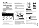
• For installation of the adapter P.C. board and removal of the relay cable, be sure to wait for a while (approx. 1 minute) after
turning off the power supplies of the air conditioner and the collective control remote controller. If not doing so, the adapter
P.C. board may be damaged.
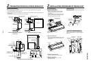
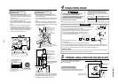
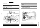
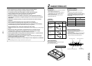
In case of 4-way Ceiling Cassette (RAV-SM
**
0 UT-E)
Relay cable (A)
Relay cable (B)
CN02
(Blue)
CN03
(Red)
CN01
(White)
CN309
(Yellow)
Spacer (C)
Spacer (C)
Spacer (C)
Indoor P.C. board A, B terminal block for remote controller Transformer box
X, Y relay terminal block
Network adapter
P.C. board
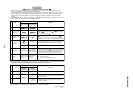
No.
1
2
3
4
Procedure
Using the spacer (C), install the adapter P.C. board to the position of the electric parts box of the indoor unit.
Using the 2 pcs. Ø4 x 14 tapping tight screws, install X, Y relay terminal block to the position of the electric parts box.
• When tightening the screws, be sure not to damage the cable.
Using 2 pcs. Ø4 x 6 tapping screws, install the transformer box storing the transformer to the position at side of the
bell mouth.
Using the relay cable (A), connect the X, Y relay terminal block with CN03 (Red) of the adapter P.C. board, and
remote controller terminal block (A, B) with CN02 (Blue) of the adapter P.C. board using the relay cable (B), respectively.
Perform cabling between the yellow connector of the transformer and CN309 of the adapter P.C. board, and between
white connector to CN01 of the adapter P.C. board, respectively.
Details
Adapter TCB-PCNT20E sold separately
* To install the adapter P.C. board to the electric parts box, put 3 pcs. spacer (C) into the hole of the P.C. board.
* After connection of the relay cables (A) and (B), fix them along the neighboring cables with bundling band so that
cables are not caught.
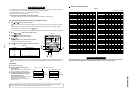
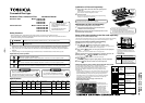
CAUTION :
Be sure that lead wire of the transformer
is not caught in between the transformer
cover and the transformer base.
Transformer base
Transformer cover
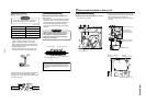
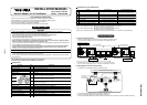
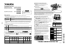
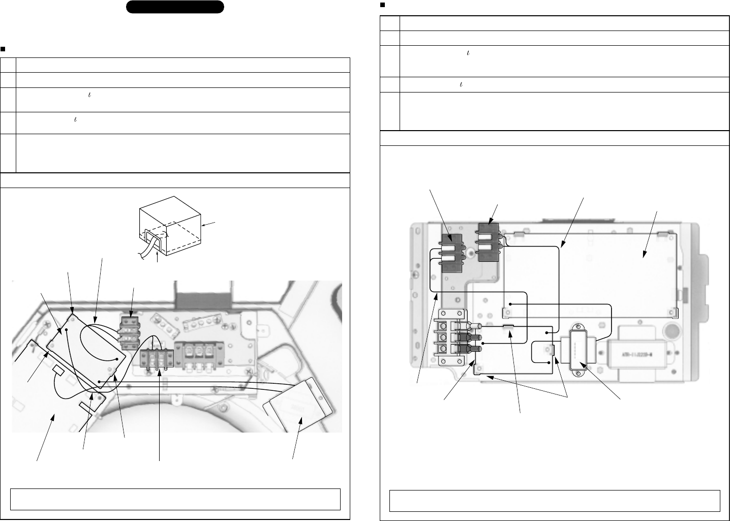
In case of Concealed Duct (RAV-SM
**
0 BT-E)
CN309 (Yellow)
A, B terminal block for remote controller
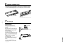
Relay cable (A)
Spacer (B) 1 pc.
Network adapter P.C. board
Transformer for network adapters
Spacer (A) 2 pcs.
Relay cable (B)
X, Y relay terminal block
Indoor P.C. board
38001
CN02
(Blue)
CN03
(Red)
CN01 (White)
No.
1
2
3
4
Procedure
Using the spacer (A) and (B), install the adapter P.C. board to the position of the electric parts box.
Using the 2 pcs. Ø4 x 14 tapping tight screws, install X, Y relay terminal block to the position of the electric parts box of
the indoor unit.
• When tightening the screws, be sure not to damage the cable.
Using 2 pcs. Ø3 x 6 B-tight screws, install the transformer to the position of the electric parts box of the indoor unit.
Using the relay cable (A), connect the X, Y relay terminal block with CN03 (Red) on the adapter P.C. board, and
remote controller terminal block (A, B) with CN02 (Blue) on the adapter P.C. board using the relay cable (B), respectively.
Perform cabling between the yellow connector of the transformer and CN309 on the indoor P.C.board, and between
white connector and CN01 on the adapter P.C. board, respectively.
Details
Adapter TCB-PCNT20E sold separately
• Relay cable (A): Connection between X, Y terminal block and CN03 on the adapter P.C. board
• Relay cable (B): Connection between terminal block of the remote controller and CN02 on the adapter P.C. board
* To install the adapter P.C. board to the electric parts box, put 2 pcs. spacers (A) into the hole of the P.C.board
(At upper side and at lower right side of the P.C.board), and install one of them to the electric parts box
(At lower left side of the P.C.board) using the board installing spacer (B) of a type which pinches the P.C.board.
* After connection of the relay cables (A) and (B), fix them along the neighboring cables with bundling band so that
cables are not caught.
TCB-PCNT20E