


– 173 –
6
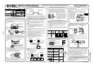
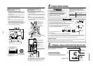
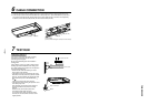
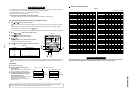
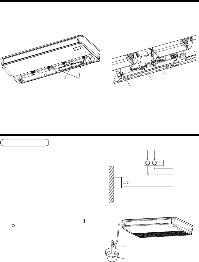
CABLE CONNECTION
1. Loosen the mounting screws (2 positions) of the cover of the electric parts box, and then remove the cover.
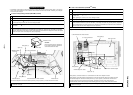
2. In the drain up kit, connect the connector (Blue 3P) for drain pump to P.C. board CN68 (Blue 3P) of the indoor
unit, and the connector (Red 3P) for float switch to P.C. board CN34 (Red 3P) of the indoor unit respectively.
In this time, remove 3P connector (Red 3P) for short-circuit of CN34 (Red 3P).
CN68 (Blue 3P)
P.C. board
CN34 (Red 3P)
(Connect while removing 3P connector for short-circuit.)
Electric parts box
2 screws
7
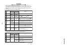
TEST RUN
Check the draining
In the test run, check that water drain is properly
performed and water does not leak from the
connecting part of the pipes.
Be sure to check draining also when installed in
heating period.
Using a pitcher or hose, pour water (1200cc) into the
discharge port before installation of the ceiling panel.
Pour water gradually so that water does not spread on
the motor of the drain pump.
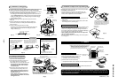
• After the electric work has finished, pour water
during COOL mode operation.
• If the electric work has not yet finished, pull out the
float switch connector (CN34 : Red) from the electric
parts box, and check draining by plugging the single
phase 220–240V power to the terminal blocks
and .
If doing so, the drain pump motor operates.
• Test water drain while checking the operation sound
of the drain pump motor.
(If the operation sound changes from continuous
sound to intermittent sound, water is normally
drained.)
After the check, the drain pump motor runs,
connecting the float switch connector.
(In case of check by pulling out the float switch
connector, be sure to return the connector to the
original position.)
Single phase 220–240V
White
Black
CN34
(RED)
Black
Red
Pull out connector CN34 (Red) from P.C. board.
1 2
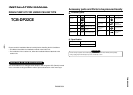
Pump for oil-heater
Bucket
TCB-DP22CE