


– 160 –
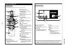
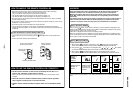
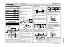
Forced ON switch
ON OFF ON OFF
Program
weekly
timer
4
wires
DC12V
Remote
controller
Indoor
unit
Outdoor
unit
: Terminal block : Connector
To terminal block
for indoor unit
remote controller
cabling
To program
weekly timer
To remote controller
Attached
connecting cable
Connector
section
Remote
controller
Timer terminal Timer terminal
Program
weekly
timer
Connecting cable (Accessory)
1
2
3
4
1
2
3
4
1
2
3
4
1
2
3
4
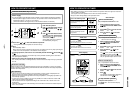
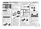
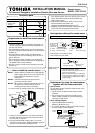
Cover
Rear case
Spacer
Small screws
M4 x 25 (2 pcs.)
or wood screws
Program weekly
timer body
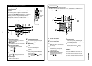
92.5mm or more
from the wall
125mm or more
90mm or more
from the wall
125mm or more
Pull-out port
of lead wire
Wall
2.5mm (Gap size)
Spacer
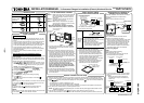
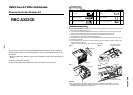
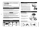
Q’ty
Part Name
1
1
2
2
2
1
1
Program weekly timer
Connecting cable
(Length: 1.2m)
Screws
M4 x 25
Spacer
Owner’s Manual
Installation Manual
Wood screws
INSTALLATION MANUAL
To Personnel Charged in Installation (Electric) Work and Service
Program Weekly Timer
MODEL : RBC-EXW21E
Accessory parts
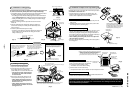
Fig. 1
*
When installing the remote controller and the
program weekly timer which are set in parallel
at upper side and lower side, in consideration
of maintenance, keep a clearance with 25mm
or more.
How to install the program weekly timer
NOTE 1 :
Avoid to twist the program weekly timer cable
with the power supply cable, etc. or to store
them in the same metal pipe, otherwise it
causes a malfunction.
NOTE 2 :
Install the program weekly timer apart from the
generation source of noise.
NOTE 3 :
When noise is induced to the power source of
the indoor unit, measures such as mounting
the noise filter is necessary.
• Install the program weekly timer to the box
(Procured locally) which has previously
inserted in the wall.
Fig. 2
1. Inserting a minus screwdriver, etc. into the
groove at the lower side of the program
weekly timer, which appears when opening
lid of the program weekly timer body, force
open the rear case to remove it.
2. Using the attached M4 screws or wood
screws (2 pcs.), fix the rear case of the
program weekly timer. Before installation,
press to open the screw hole with a
screwdriver, etc.
Fix it with the spacer, but not so strongly.
If the program weekly timer does not fit
closely to the wall, adjust it by cutting off the
spacer.
3. Connect the attached connecting cable
(4 cores) to the program weekly timer body.
4. Install the program weekly timer body by
matching to hooks on the rear case and
putting into the hooks.
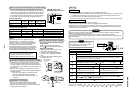
Cabling
• Connection diagram
(Be sure to use the attached connecting
cable.)
• Arrangement
The program weekly timer and the remote
controller can be arranged to either right or left
side.
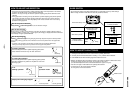
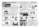
• Cabling procedure
Perform cabling in the following procedure.
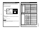
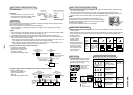
1. Connect the attached connecting cable to the
timer terminal (4P connector) of the program
weekly timer. (Fig. 3)
<Remote controller> <Program weekly timer>
BACKUP switch
ON OFF ON OFF
Attached connecting
cable
Lead wire
pull-out port
85464359429000 (EN)
Fig. 3
2. Pull the attached cable out of lead wire pull-
out port on the rear case of the program
weekly timer and connect the cable to the
timer terminal (4P connector) of the remote
controller via inside of the wall. (Fig. 4)
<Program weekly timer> <Remote controller>
Fig. 4
• System diagram
Program weekly timer test run setup
• After installation, check (OFF to ON) output
status using the forced ON switch on the rear
side of the program weekly timer P.C. board.
Then check the normal operation and
certainly turn OFF the forced ON switch.
Explanation to customers
• After the installation work, hand “Owner’s
Manual” and “Installation Manual” to the
customers.
• Explain use and maintenance methods to the
customers according to “Owner’s Manual”.
Requirement to install
the program weekly timer
Installing dimension for serial installation
When installing the program weekly timer
(remote controller/system controller, etc.) to the
wall surface, follow the installation procedure in
(Fig. 1) and (Fig. 2).
Memory backup function for
power failure compensation
• This program weekly timer stores in memory
the contents set by the operation button during
a power failure. Pushing PROGRAM button
resumes the operation with the contents
before the power failure when the power failure
has been reset.
• How to use [BACKUP]
After the installation work, check [BACKUP]
switch on the rear side of the program weekly
timer P.C. board is turned to ON side.
RBC-EXW21E