


– 163 –
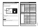
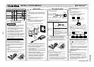
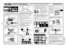
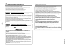
How to set the room temperature sensor
• The room temperature sensors are equipped in the indoor unit and the wireless remote controller.
One of two sensors works.
• The room temperature sensor is set to the indoor unit side at the shipment from the factory.
To select the sensor in the remote controller, push the SENSOR button (Right figure) inside of the
remote controller cover and check “Main sensor” disappears from LCD.
NOTE :
If the room temperature data from the remote controller is not
transmitted to the unit for 10 minutes or more, the sensor at indoor
unit side is automatically selected even if the sensor at the remote
controller side is selected.
Fix the remote controller toward the unit as possible.
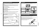
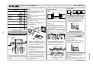
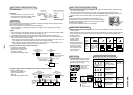
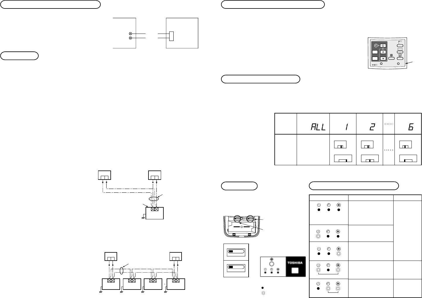
How to set the address switch
• When the multiple sensors are installed in the same room, an address can be set to prevent cross
communication.
• When replacing the battery and pushing SET button, the address of the remote controller becomes
[ALL] and the sensor is enabled to receive signal regardless of setting of address switch of the
operation section.
• For selecting of the
remote controller
address, refer to
Owner’s Manual.
• Change the address of
the sensor by removing
screws of P.C. board
cover of the sensor
unit. After then, fix the
cover with screws
using a clamp.
Slide switch
• Check the slide switch in the battery
box of the remote controller is set to
[S] / [A] at shipment from the factory.
Do not change the setting.
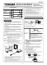
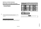
Self-diagnosis table and measures
Lamp indication
No indication even if
the remote controller
is operated.
Cause
Power supply is not
turned on.
Miscabling between
sensor unit and indoor
unit
Defective connection
between sensor unit
and indoor unit
Miscabling or defective
connection between
indoor and outdoor
units
Protective device of
outdoor unit works.
Protective device of
indoor unit works.
Measures
Che
ck cable
connection
and correct it.
Check
outdoor unit.
Check
indoor unit.
Lamp indication of sensor
: Goes off
: Flash
(0.5-sec. interval)
SET
ACL
SENSOR
CL
ADR
Sensor
button
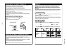
S001
4–6
S002
3
6
2
5
1
4
Address
select
Address
S002
3
6
2
5
1
4
Address
S002
3
6
2
5
1
4
Address
S001
4–6
Address
select
S001
4–6
Address
select
Display of
remote
controller
address
Address
switch
position of
sensor
*Address switch
of sensor unit
can be set any
position.
Address Address Address Address
1–31–31–3
SKN AHC
Select of operation
mode set to A.
Select of flap
indication set to S.
AHC
SKN
Flashes alternatively
Flashes alternatively
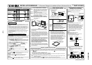
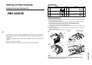
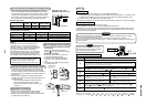
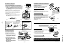
How to perform cabling of sensor units
Connection diagram
Connection
• Connect the cables out of the sensor unit to
the terminal block for remote controller cabling
of the indoor unit. (There is no polarity.)
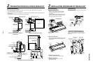
Requirement
The control by two remote controllers is enabled by installing the wireless remote controller with the
wired remote controller for an indoor unit.
(Max. 2 remote controllers of wireless or wired are installable.)
“2-remote controllers” controlling means that one or multiple units are operated by the multiple
remote controllers.
NOTES :
1. Upon confirmation of the terminal numbers of the indoor unit, connect the remote controller cables
without miscabling. (If applied AC 220–240 Volt, damage the unit.)
2. The multiple wireless remote controller kits cannot concurrently be used for an indoor unit.
3. When installing simultaneously the wireless remote controller with the wired remote controller, set
one of them as the sub remote controller.
• When setting the wired remote controller as the sub, exchange the address connector at the rear
of P.C. board of wired remote controller from master to sub remote controller.
• When setting the wireless remote controller as the sub, turn No.3 of DIP switch [S003] on P.C.
board of wireless remote controller sensor unit from OFF to ON.
To operate an indoor unit by 2 remote controllers
*
The indoor unit is operated if
either wireless or wired remote
controller is set as master or
sub remote controller.
(Total cable length: Within 400m)
To operate a group control of multiple indoor units by 2 remote controllers
*
Master and Sub remote
controllers are operable even
if they are installed to any
indoor unit.
(Total cable length: Within 200m)
CN001
2P White
Indoor unit Sensor unit P.C. board
Terminal block for
remote controller
cabling
White
Black
Earth
Wireless
remote controller kit
(Master)
CN1
Wired
remote controller
(Sub)
21
(Sold separately)(Sold separately)
Terminal block for
remote controller cable
Remote controller cable
(Procured locally)
(0.5 to 2mm²)
Indoor unit
21
Sensor
unit
Earth Earth Earth
(Sold
separately)
(Sold
separately)
Terminal block
for remote
controller
cable
Remote controller inter-unit
cable for group control
(Procured locally)
(0.5 to 2mm²)
21
Wired
remote controller
(Sub)
Wireless
remote controller kit
(Master)
CN1
21
Indoor unit
No.1
Indoor unit
No.2
Indoor unit
No.3
Earth
Indoor unit
No.N
Sensor
unit
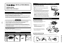
RBC-AX22CE