– 152 –
NAME AND OPERATION
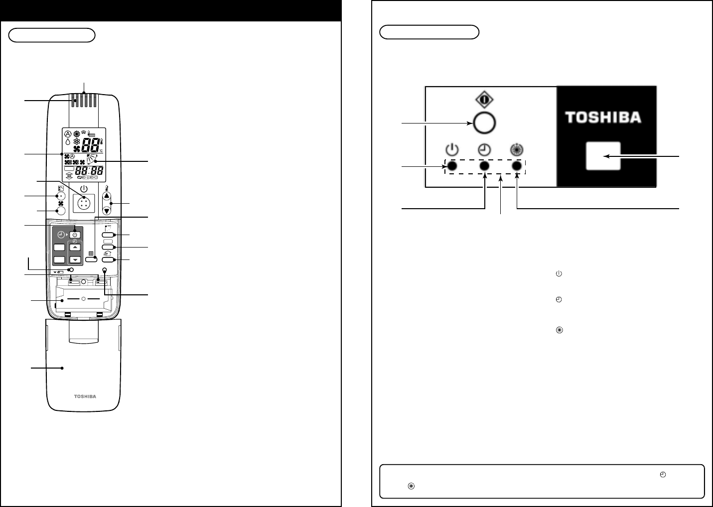
Remote Controller
• Max. 8 indoor units can be operated by a remote controller as a group.
1
Transmitting part
2
Remote controller sensor
The peripheral temperature is sensed when
the sensor button is pushed to remote
controller side.
3
Mode display section
The operation mode is displayed.
4
Start/Stop button
Pushing this button starts, and pushing
again stops the unit.
5
Mode Select button
Pushing this button selects an operation
mode.
6
Air volume button
7
Time Setup button
This button is used when the timer is
setup.
8
Reset button
This button is used after replacement of
battery or selection of slide switch.
9
Slide switch
10
Part storing batteries
11
Cover
Slide the cover holding its both sides.
12
AUTO flap display differs according
to the installed unit.
13
Setup Temp. button
Every pushing this button, temperature
rises by 1˚C.
Every pushing this button, temperature
lowers by 1˚C.
14
Filter button
The remote controller is not operated
even if this switch is pushed.
15
Swing/Air direction button
16
Address button
17
Ventilation button
The remote controller is not operated
even if this switch is pushed.
18
Sensor button
This button is used when selecting the
temp. sensor at the remote controller
side. At the shipment from the factory,
this button is set to the temp. sensor at
the indoor unit.
SET
ACL
SENSOR
CL
SKN AHC
ADR
ADR
1
2
4
6
8
5
7
9
10
11
14
3
16
13
12
15
17
18
• The signal receiving part is mounted to the ceiling panel.
Signal Receiving Part
1
Temporary operation button
2
Signal receiving part
The signal sent from the remote control-
ler is received.
3
Display lamp
One of displays flashed while a trouble
occurs. When the display lamp flashes,
refer to “Before asking of repair”
.
• If “pi, pi” sound is heard, the MODE lamp of the display lamp goes on, and the lamp
and
lamp flash alternately, the operation is not performed with the desired mode.
4
lamp
This lamp goes on during operation.
5
lamp
This lamp goes on while the timer is
reserved.
6
lamp
• In heating operation this lamp in the
following cases;
The operation has started.
The temp. controller has worked.
The unit is under defrost operation.
• This lamp flashes while a trouble occurs.
1
4
5
3
6
2
RBC-AX22CE


