


– 111 –
RAV-SM560, 561, 800, 801BT-E
RAV-SM1101, 1401BT-E
7
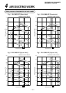
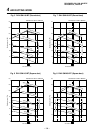
EVACUATING
Hexagonal wrench is required.
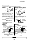
AIR PURGE
Evacuate the air in the connecting pipes and in the
indoor unit using vacuum pump.
Do not use the refrigerant in the outdoor unit.
For details, see the manual of vacuum pump.
Use a vacuum pump
Be sure to use a vacuum pump with counter-flow
prevention function so that inside oil of the pump does
not flow backward into pipes of the air conditioner
when the pump stops.
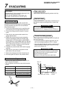
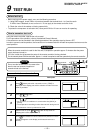
1. Connect the charge hose from the manifold valve
to the service port of the gas side packed valve.
2. Connect the charge hose to the port of vacuum
pump.
3. Open fully the low pressure side handle of the
gauge manifold valve.
4. Operate the vacuum pump to start evacuating.
Perform evacuating for about 35 minutes if the
piping length is 30 meters total for model SM560
and 50 meters for model SM800, SM1100, SM1400
(assuming a pump capacity of 27 liters per minute.)
Then confirm that the compound pressure gauge
reading is –101 kPa ( –76 cmHg).
5. Close the low pressure side valve handle of gauge
manifold.
6. Open fully the valve stem of the packed valves
(both sides of Gas and Liquid).
7. Remove the charging hose from the service port.
8. Securely tighten the caps on the packed valves.
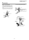
Packed valve handling precautions
• Open the valve stem all the way out ; do not try to
open it beyond the stopper.
• Securely tighten the valve stem cap at the torque as
follows:
15.9 mm (diam.)
12.7 mm (diam.)
9.5 mm (diam.)
6.4 mm (diam.)
68 to 82 N•m (6.8 to 8.2 kgf•m)
50 to 62 N•m (5.0 to 6.2 kgf•m)
33 to 42 N•m (3.3 to 4.2 kgf•m)
14 to 18 N•m (1.4 to 1.8 kgf•m)
Open valve fully
Open valves of the corresponding outdoor units fully.
Gas leak check
Using a lead detector or soap water, check there is no
gas leak from pipe connecting portion or caps of the
valves.
REQUIREMENT
For a leak detector, use one manufactured
exclusively for HFC refrigerant (R410A, R134a, etc.)
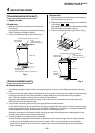
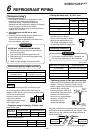
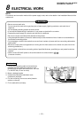
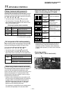
Thermal-insulating process
Perform pipe thermal-insulating process for liquid and
gas sides separately.
• For thermal insulator to pipes at gas side, use one
with heat resisting temperature 120°C or higher.
• Using the attached thermal insulator, perform surely
thermal insulation without gap for pipe connecting
portion of the indoor unit.
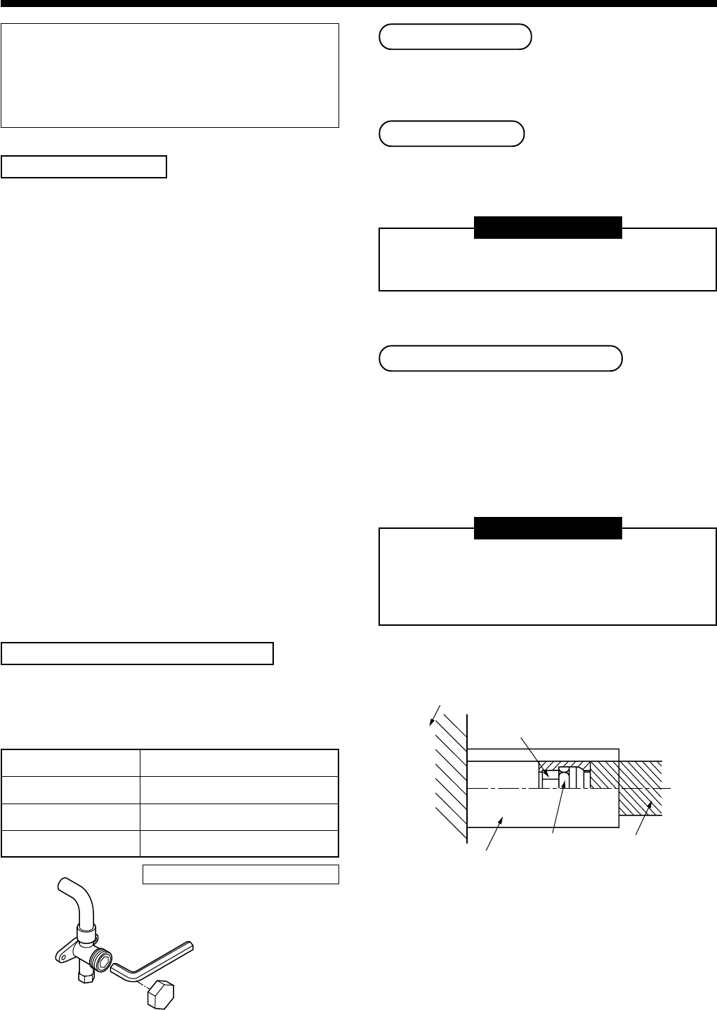
REQUIREMENT
Perform surely thermal insulation process so that
the naked end of pipe connecting portion of the
indoor unit does not appear.
(Exposure of the pipe may cause water leak.)
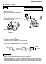
Main unit
Union
Attached thermal insulator
Flare nut
Pipe thermal
insulator