


– 167 –
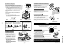
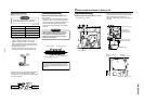
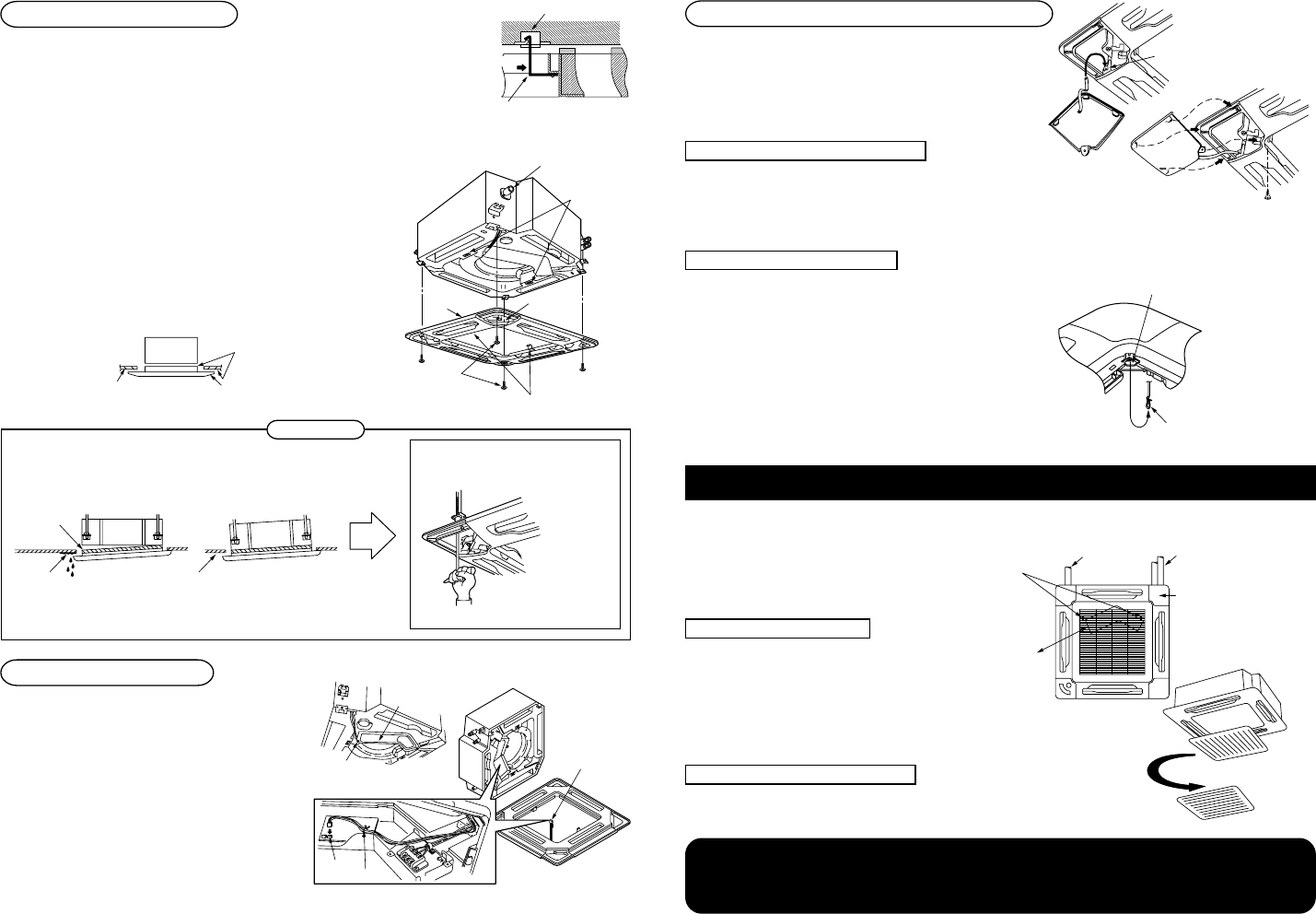
(3) Installation of ceiling panel
The angle change of the flap is possible while the power supply is turned
on. (Do not move forcibly the flap with hands. It may break the flap.)
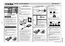
1. For tentative hanging, insert the tentative hanging metal (stainless) inside of
the ceiling panel into the square hole of the indoor unit. (Fig. 2)
• The ceiling panel has directional ability against the indoor unit. Direct the
mark of refrigerant pipe at the ceiling panel corner toward the pipe side.
• Holding the ceiling panel, remove it while pushing the tentative hanging
metal toward the outside.
Corner of drain pipe
Square hole
of indoor unit
Ceiling panel
Draining
mark
Screw
with washer
Tentative hanging metal
Mark of
refrigerant pipe
Square hole of indoor unit
Tentative hanging metal
Push to remove
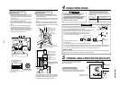
Indoor unit
No clearance
Ceiling panelCeiling surface
2. Match the mounting hole of the panel with the screw hole of the
indoor unit.
3. Using the attached screws with washer, tighten 4 positions at
corners of the suction port until the panel is fitted closely to the
main unit. (Fig. 3)
4. Check the panel is fitted closely to the ceiling.
• In this time, check there is no clearance between the indoor unit
and the ceiling panel, and between the ceiling panel and the
ceiling surface. (Fig. 4)
(Fig. 2)
(Fig. 3)
(Fig. 4)
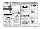
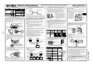
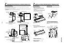
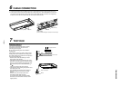
(4) Cabling of ceiling panel
1. Open cover of the electric parts box.
2. Connect the flap motor wiring connector out
of the ceiling panel to the connector 5P
(CN33: white) on P.C. board of the indoor unit.
• Connect the connector surely because
the flap does not work if the connector
is not connected.
3. Mount cover of the electric parts box in the
reverse procedure of opening of the cover.
• Check whether the wiring connector is
pinched between the electric parts box
and the cover or not.
• Check whether the wiring connector is
pinched between the indoor unit and the
ceiling panel or not.
As shown in the figure, pass the clamping material through inside of the slit.
After connection, store the connector section in the electric parts box.
Wiring explanation diagram
(For explanation, direction of the indoor unit is changed.)
Electric parts box cover
Screws
(3 positions)
Flap motor
wiring connector
Clamper
CN33
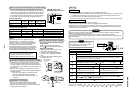
• Tighten the screws securely because
a trouble is caused as shown in the
following figure if the screws are
incompletely tightened.
• When there is a clearance between the
ceiling surface and the ceiling panel
even if the screws have been tightened,
readjust height of the indoor unit.
Air leak
Air leak
from ceiling
Generation
of dust
Dewing/water
leak
Adjust so that there is
no clearance.
The height of the indoor unit can be adjusted from
corner hole on the ceiling panel as the ceiling panel
is installed if the adjustment does not affect the
levelness of the indoor unit, drain pipe, etc.
After adjustment, be sure to tighten the
mounting nut of the indoor unit securely.
CAUTIONS
(Fig. 5)
(Fig. 6)
(Fig. 7)
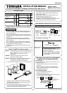
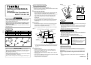
(5) Installation of adjust corner cap/suction grille
Install the adjust corner cap/suction grille in the reverse procedure
of installation to the indoor unit.
• For this ceiling panel, as shown in the following figure, the
direction of the suction grille can be changed on customer’s
demand when multiple indoor units are installed.
A. Installation of adjust corner cap
1. Hook the strap of the adjust corner cap surely to the pin on the
ceiling panel.
2. Install the adjust corner cap to the ceiling panel, and fix it with
the mounting screws. (accessory part)
B. Installation of suction grille
• To install the suction grille, follow to the reverse procedure of the
removal. This ceiling panel can be installed from anyone of 4
directions by turning the suction grille. Change the direction on
the customer’s demand or according to the direction matching of
the suction grille when multiple units are installed.
• When installing the suction grille, be sure not to pinch the
flap motor wiring connector.
• Be sure to attach a strap to prevent falling of the suction grille to
the ceiling panel.
3. Others
After confirmation of the above items, hand a set of this manual, manuals for the indoor unit,
manual for products sold separately, etc. to the customer. For cleaning of the filter, be sure to
ask the maintenance professional.
Pin
Install the adjust corner cap horizontally
to the ceiling surface so that 3 hooks of
the adjust corner cap are set in holes of
the ceiling panel. And then fix it with the
mounting screws (accessory part).
A. Check after installation
• Check again there is no clearance between the
indoor unit and the ceiling panel, and between
the ceiling panel and the ceiling surface.
*
A clearance causes water leak or dewing.
• Check the cables are connected surely.
*
Incomplete connection causes a trouble such as the flap does not work.
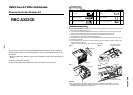
B. For wireless remote controller
• For details of installation, refer to the Installation Manual attached to the
wireless remote controller kit (sold separately).
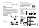
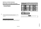
Positions of suction grille hooks at shipment from the factory
*
Although the suction grille can be installed from any
position of 4 corners, these positions are recommended.
It is unnecessary to remove the suction grille in
maintenance for the electric parts box of the indoor unit.
( )
Refrigerant pipe
side of indoor unit
Drain pipe side
of indoor unit
Electric parts box
of indoor unit
Wireless remote
controller kit
(sold separately)
Direction-free in 360˚
EH99708701-(1) (EN)
(Fig. 8)
(Fig. 9)
Hook hole of
ceiling panel
Hook of
fall-preventive strap
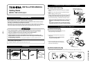
RBC-U21PG (W)-E