


Getting StartedTeledyne API – Model T300/T300M CO Analyzer
Teledyne Analytical Instruments 66
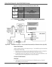
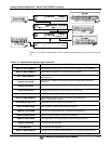
Table 3-9: Zero/Span Valve Operating States for Option 50B
MODE VALVE CONDITION
SAMPLE
(Normal
State)
Sample/Cal Open to SAMPLE inlet
Zero/Span Open to IZS inlet
Shutoff Valve Closed
ZERO CAL
Sample/Cal Open to ZERO/SPAN valve
Zero/Span Open to IZS inlet
Shutoff Valve Closed
SPAN CAL
Sample/Cal Open to ZERO/SPAN valve
Zero/Span Open to SHUTOFF valve
Shutoff Valve Open to PRESSURE SPAN Inlet
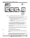
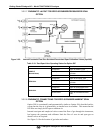
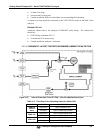
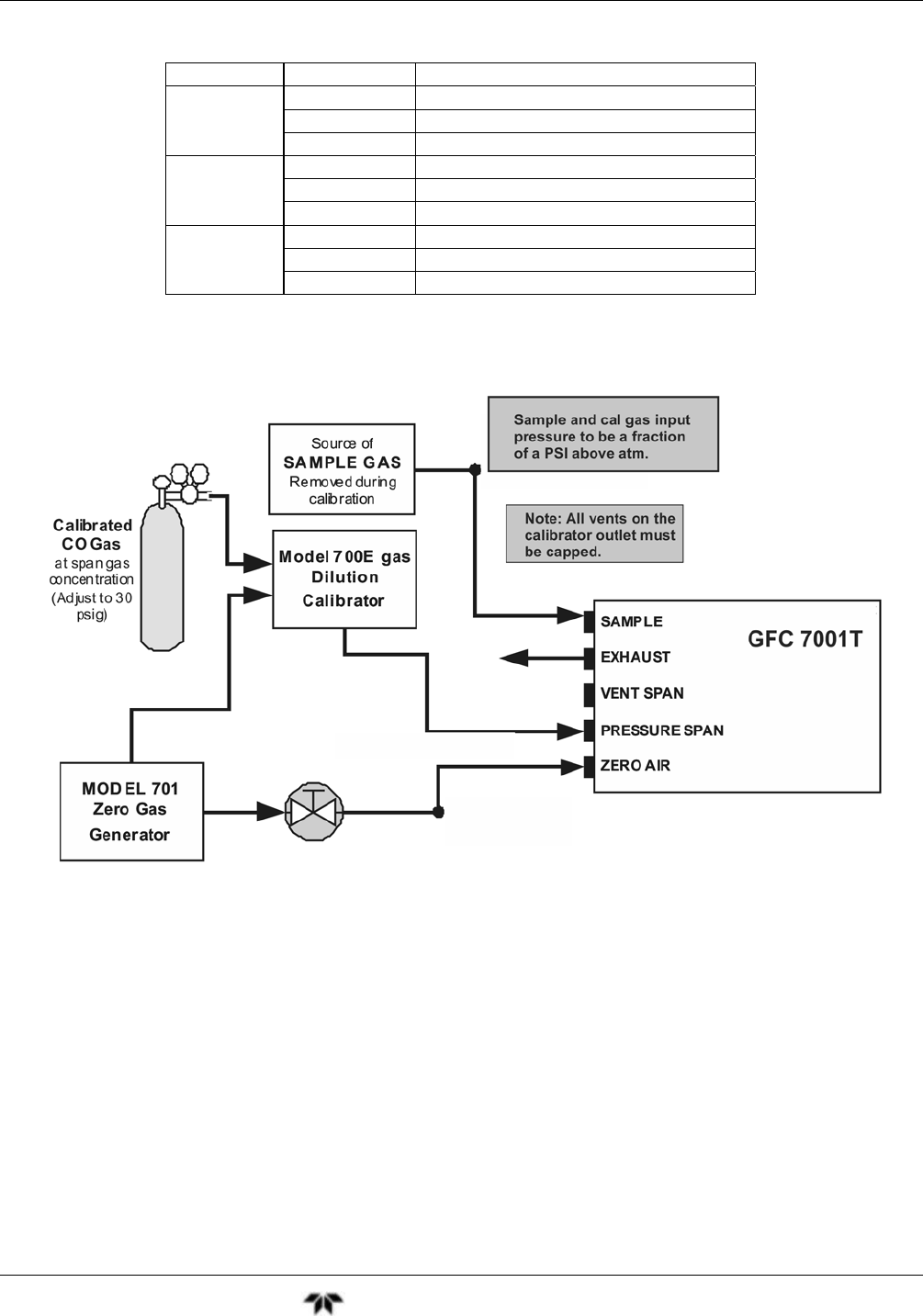
3.3.2.6. PNEUMATIC CONNECTIONS FOR ZERO SCRUBBER/PRESSURIZED
SPAN OPTION
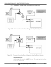
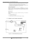
Figure 3-24: Pneumatic Connections – Zero Scrubber/Pressurized Span Calibration Valves (Opt 50E)
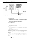
SAMPLE GAS SOURCE
Attach a sample inlet line to the sample inlet port. The SAMPLE input line should not
be more than 2 meters long.
Maximum pressure of any gas at the sample inlet should not exceed 1.5 in-hg above
ambient pressure and ideally should equal ambient atmospheric pressure.
In applications where the sample gas is received from a pressurized manifold, a vent
must be placed on the sample gas before it enters the analyzer.
C
ALIBRATION GAS SOURCES
S
PAN GAS:
Attach a gas line from the pressurized source of calibration gas (e.g. a bottle of
NIST-SRM gas) to the span inlet.