Theory of Operation Teledyne API – Model T300/T300M CO Analyzer
Teledyne Analytical Instruments 307
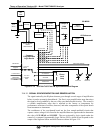
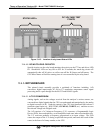
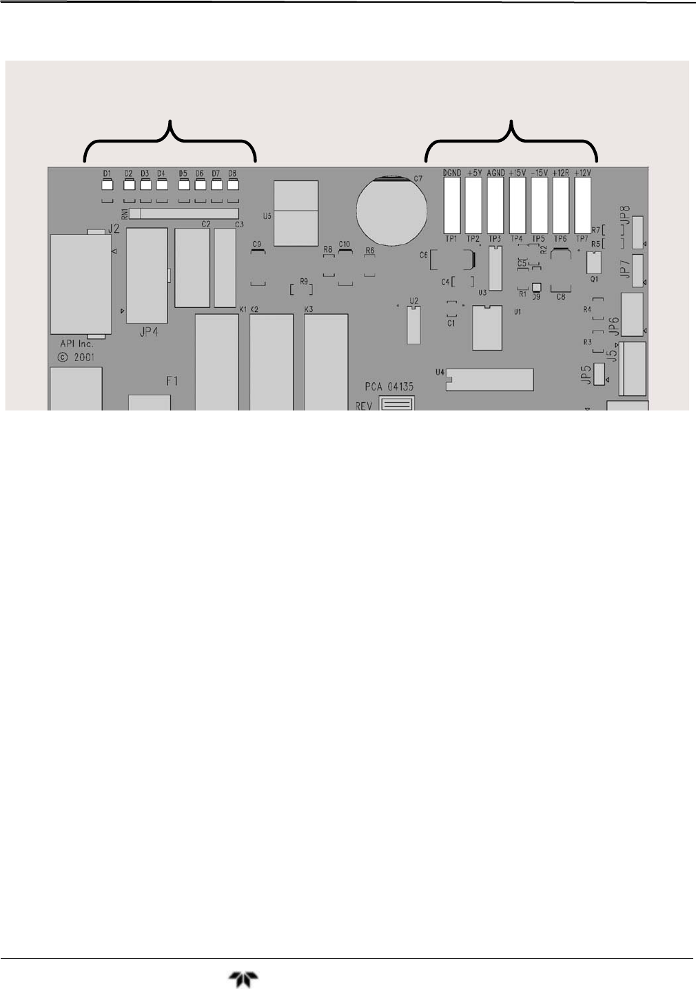
STATUS LED’s
DC VOLTAGE TEST
POINTS
RELAY PCA
PN 04135
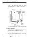
Figure 13-15: Location of relay board Status LEDs
13.4.4.6. I2C WATCH DOG CIRCUITRY
Special circuitry on the relay board monitors the activity on the I
2
C bus and drives LED
D1. Should this LED ever stay ON or OFF for 30 seconds, the watch dog circuit will
automatically shut off all valves as well as turn off the IR Source and all heaters. The
GFC Wheel motor will still be running since it is not controlled by the relay board.
13.4.5. MOTHERBOARD
This printed circuit assembly provides a multitude of functions including, A/D
conversion, digital input/output, PC-104 to I
2
C translation, temperature sensor signal
processing and is a pass through for the RS-232 and RS-485 signals.
13.4.5.1. A TO D CONVERSION
Analog signals, such as the voltages received from the analyzer’s various sensors, are
converted into digital signals that the CPU can understand and manipulate by the analog
to digital converter (A/D). Under the control of the CPU, this functional block selects a
particular signal input (e.g. BOX TEMP, CO MEAS, CO REF, etc.) and then coverts
the selected voltage into a digital word.
The A/D consists of a Voltage-to-Frequency (V-F) converter, a Programmable Logic
Device (PLD), three multiplexers, several amplifiers and some other associated devices.
The V-F converter produces a frequency proportional to its input voltage. The PLD
counts the output of the V-F during a specified time period, and sends the result of that
count, in the form of a binary number, to the CPU.


