


Theory of Operation Teledyne API – Model T300/T300M CO Analyzer
Teledyne Analytical Instruments 304
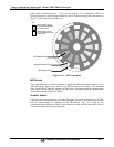
The four sample and hold circuits are designated as follows:
Table 13-2: Sync DEMOD Sample and Hold Circuits
Designation
Active When:
IR BEAM PASSING THROUGH Segment Sensor Pulse is:
Measure Gate MEASUREMENT cell of GFC Wheel HIGH
Measure Dark Gate MEASUREMENT Cell of GFC Wheel LOW
Reference Gate REFERENCE cell of GFC Wheel HIGH
Reference Dark Gate REFERENCE cell of GFC Wheel LOW
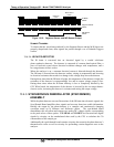
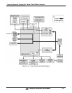
Timing for activating the Sample and Hold Circuits is provided by a Phase Lock Loop
(PLL) circuit. Using the segment sensor output as a reference signal the PLL generates
clock signal at ten times that frequency. This faster clock signal is used by the PLD to
make the Sample and Hold Circuits capture the signal during the center portions of the
detected waveform, ignore the rising and falling edges of the detector signal.
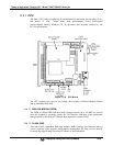
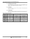
Sample & Hold
Active
Detector
Output
Sample & Hold
Inactive
Figure 13-14: Sample & Hold Timing
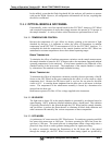
13.4.3.2. SYNC/DEMOD STATUS LEDS
The following two status LEDs located on the sync/demod board provide additional
diagnostic tools for checking the GFC Wheel rotation.
Table 13-3: Sync/Demod Status LED Activity
LED Function Status OK Fault Status
D1 M/R Sensor Status
LED flashes approximately
2/second
LED is stuck
ON or OFF
D2 Segment Sensor Status
LED flashes approximately
6/second
LED is stuck
ON or OFF
See Section 12.1.4.2 for more information.
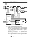
13.4.3.3. PHOTO-DETECTOR TEMPERATURE CONTROL
The sync/demod board also contains circuitry that controls the IR photo-detector’s
Thermal Electric Coolers (TEC). A drive voltage, PHT DRIVE, is supplied to the