


Troubleshooting and ServiceTeledyne API – Model T300/T300M CO Analyzer
Teledyne Analytical Instruments 279
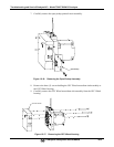
12.5.8.5. CONTROL INPUTS – REMOTE ZERO, SPAN
The control input bits can be tested by the following procedure:
1. Jumper the +5 pin on the Status connector to the U on the Control In connector.
2. Connect a second jumper from the
_
pin on the Status connector to the A pin on the
Control In connector. The instrument should switch from Sample Mode to ZERO
CAL R mode.
3. Connect a second jumper from the
_
pin on the Status connector to the B pin on the
Control In connector. The instrument should switch from Sample Mode to SPAN
CAL R mode.
4. In each case, the GFC7001T/GFC7001TM should return to Sample Mode when the
jumper is removed.
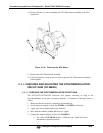
12.5.9. CPU
There are two major types of CPU board failures, a complete failure and a failure
associated with the Disk On Module (DOM). If either of these failures occurs, contact
the factory.
For complete failures, assuming that the power supplies are operating properly and the
wiring is intact, the CPU is faulty if on power-on, the watchdog LED on the
motherboard is not flashing.
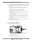
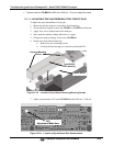
In some rare circumstances, this failure may be caused by a bad IC on the motherboard,
specifically U57, the large, 44 pin device on the lower right hand side of the board. If
this is true, removing U57 from its socket will allow the instrument to start up but the
measurements will be invalid.
If the analyzer stops during initialization (the front panel display shows a fault or
warning message), it is likely that the DOM, the firmware or the configuration and data
files have been corrupted.
12.5.10. RS-232 COMMUNICATIONS
12.5.10.1. GENERAL RS-232 TROUBLESHOOTING
TAI analyzers use the RS-232 communications protocol to allow the instrument to be
connected to a variety of computer-based equipment. RS-232 has been used for many
years and as equipment has become more advanced, connections between various types
of hardware have become increasingly difficult. Generally, every manufacturer
observes the signal and timing requirements of the protocol very carefully.
Problems with RS-232 connections usually center around the following general areas:
1. Incorrect cabling and connectors. See Section 3.3 for connector and pin-out
information.
2. The BAUD rate and protocol are incorrectly configured. See Section 6.2.2.
3. If a modem is being used, additional configuration and wiring rules must be
observed. See Section 8.3
4. Incorrect setting of the DTE-DCE Switch. Ensure that switch is set correctly. See
Section 6.1.
5. Verify that cable (P/N 03596) that connects the serial COM ports of the CPU to J12
of the motherboard is properly seated.